Precision lens manufacturer for machine vision, medical, and industrial imaging applications.

3D Stereo Vision Optics — Matched Pairs & Profiler Lenses

Optics for Stereo Vision Cameras: Matched Pairs, Not Random Lenses

Depth accuracy starts at the glass. Lensmind supplies factory-matched stereo lens pairs (K3005A / Q1356) and 3D laser profiler optics (K2540A / K2569A) for stereo vision cameras and laser line scanners — magnification, distortion and axis consistency controlled before your calibration ever runs.

K3005A / Q1356 Matched Pairs K2540A / K2569A Profiler Optics Per-Pair Test Records ISO 9001 Factory
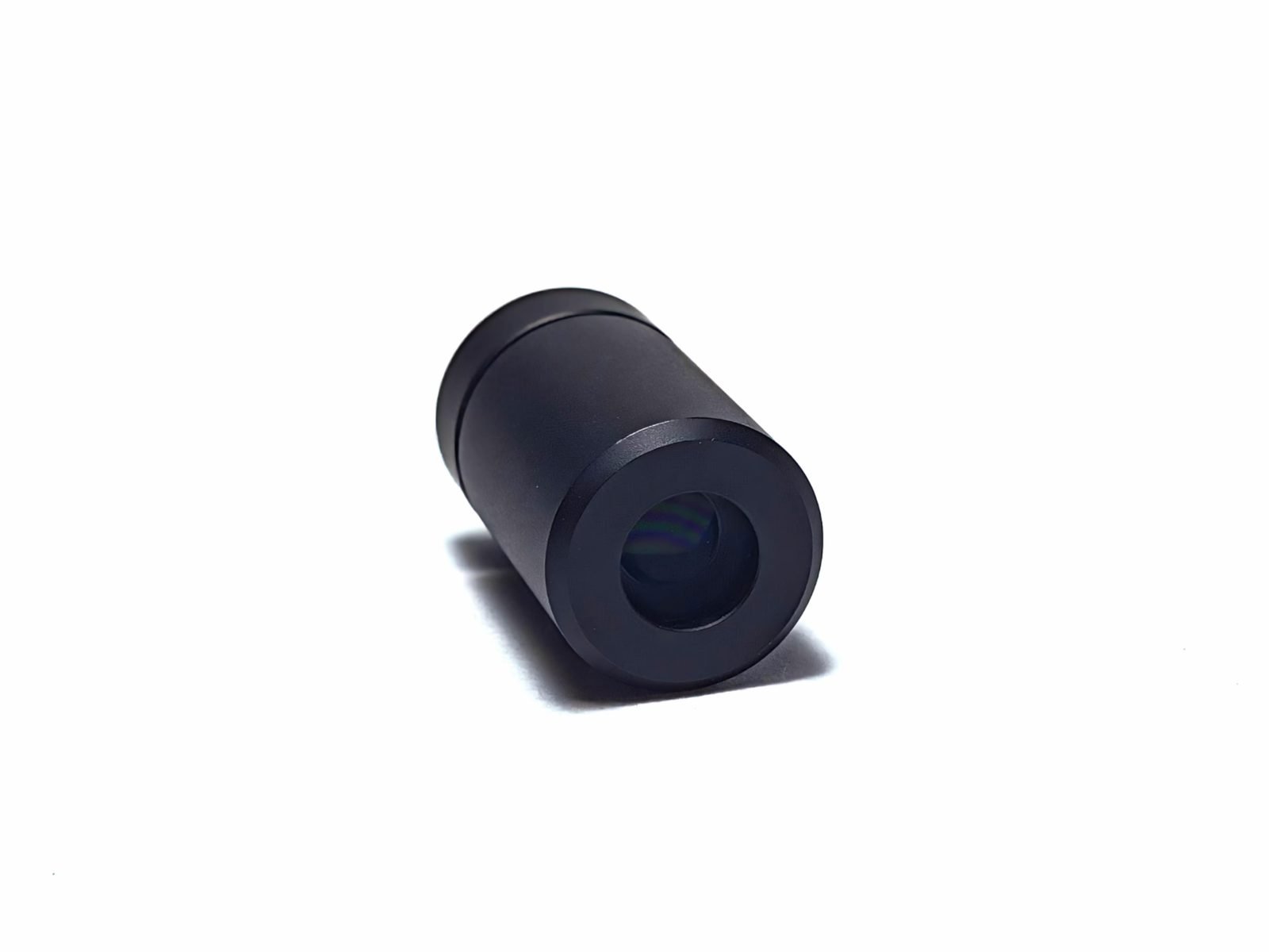
Lensmind K3005A matched stereo lens pair for stereo vision cameras, factory-paired for depth accuracy
Capability / OEM console

3D stereo and profiler optics are quoted as matched pairs and program builds. No official catalog sheet — and no invented model table on this page.

Lensmind K3005A matched stereo lens pair for stereo vision cameras, factory-paired for depth accuracy

Passive Stereo or Laser Line: The First Decision in 3D Machine Vision

Passive stereo: two synchronized cameras, depth from disparity, color and texture for free. Active laser line: a projected line, triangulation, dense height on untextured metal. We build optics for both routes as OEM programs — there is no official 3D SKU sheet on this site.

Why matching is bought at the lens →
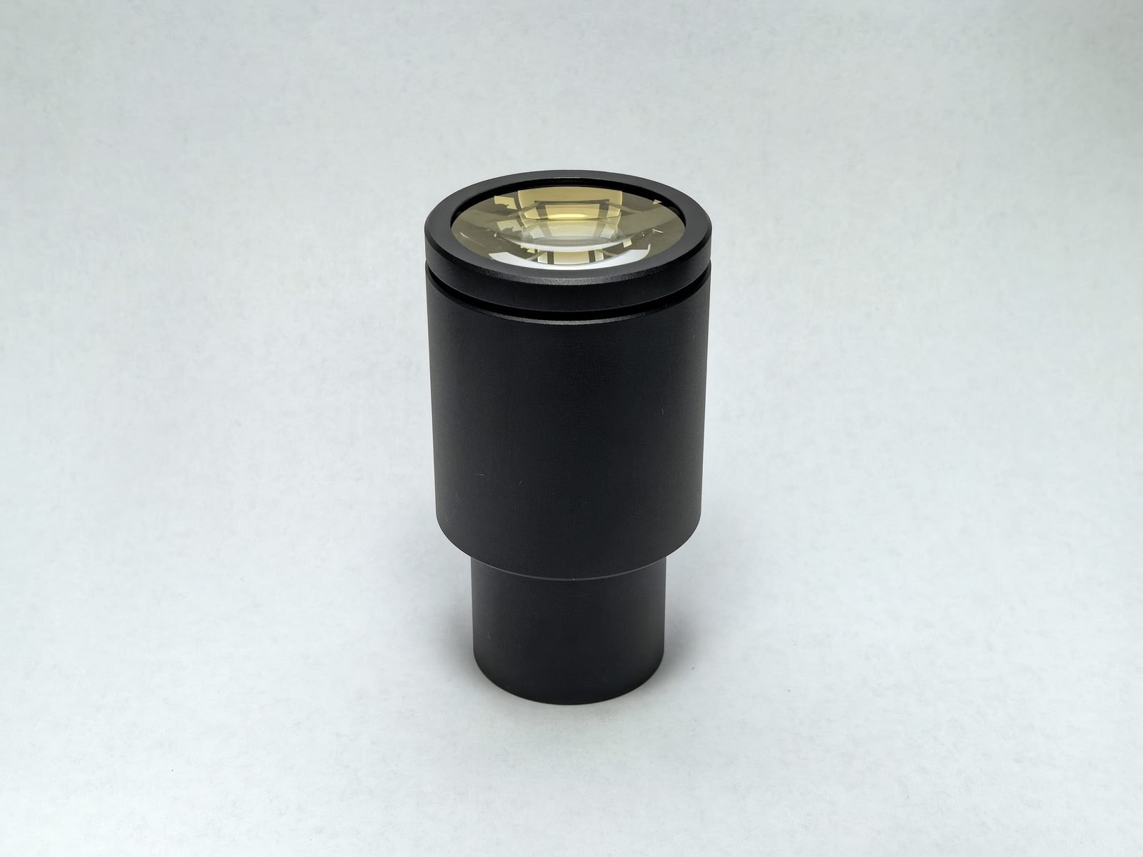
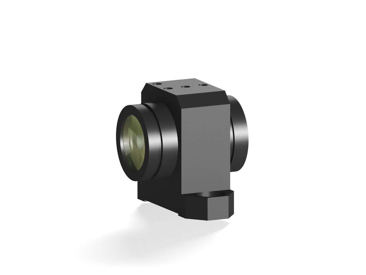
Lensmind K3005A 3d stereo vision binocular lens, product photo by Lensmind Optics

Stereo Depth Accuracy Is Bought at the Lens, Not the Software

Depth follows Z = f × B / d. Magnification mismatch, distortion-curve mismatch or axis deviation becomes disparity error, then Z-error. Factory-matched pairs are verified as a pair on Trioptics centration and the MTF bench; per-pair records ship with the order. Exact prescriptions are quoted per sensor and baseline — not listed as a fake catalog table.

Request a matched-pair proposal →
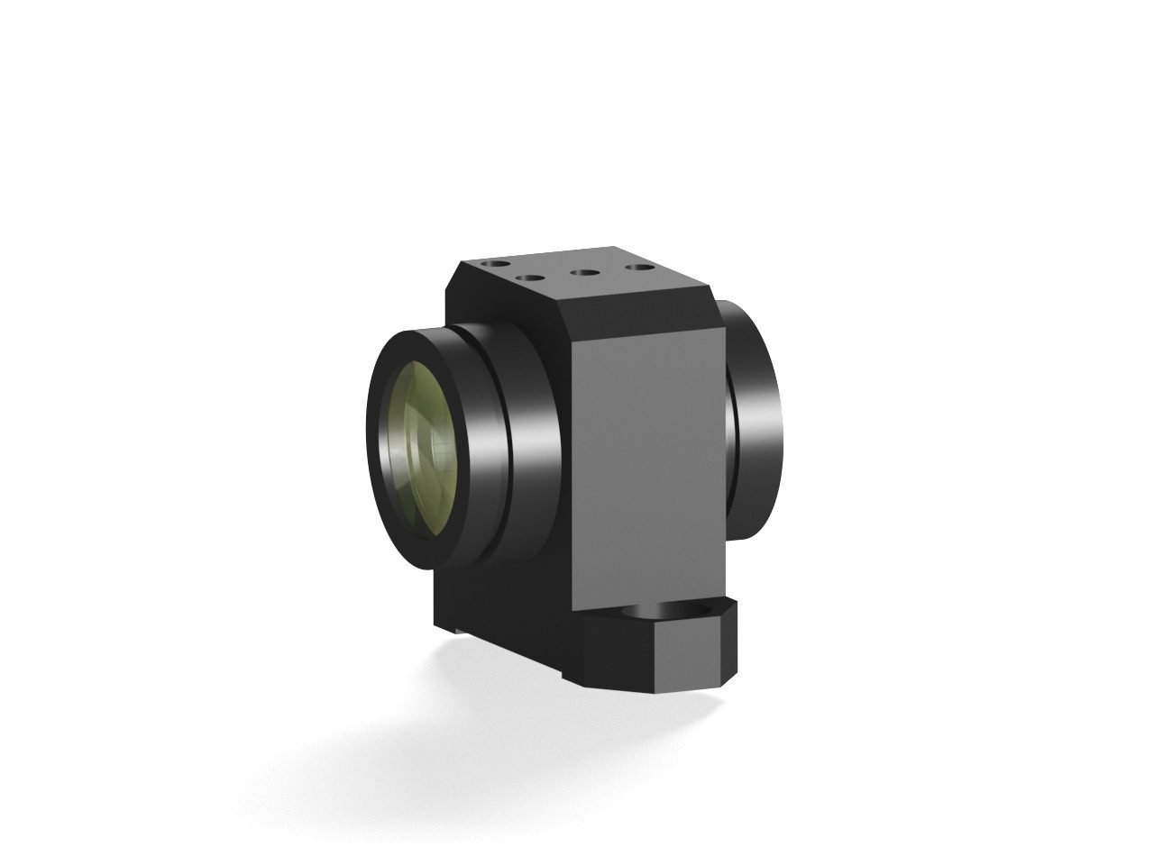
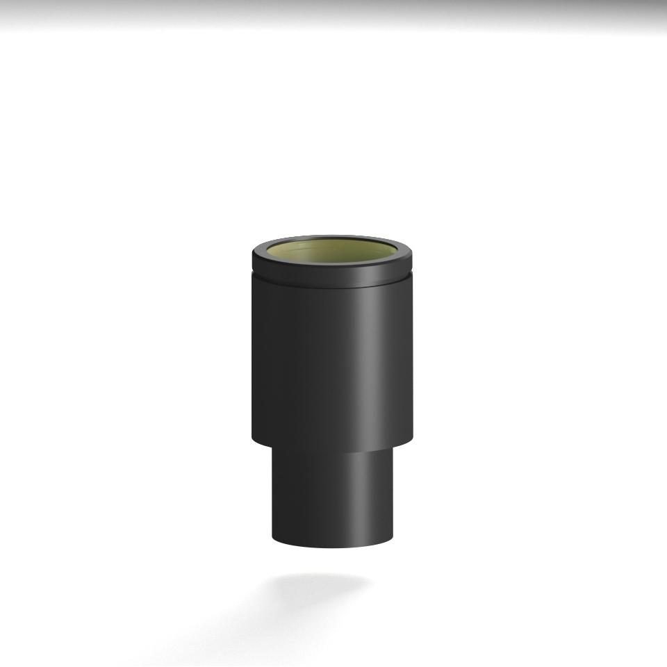
Lensmind K2540A 3d laser profiler lens, precision optics manufactured by Lensmind

K2540A & K2569A — Optics for Laser Line Scanners

Profiler optics hold triangulation geometry between projected line and sensor — high-contrast line reproduction across the measurement volume, on top of line-scan-grade imaging. Hardware on the bench is real; parameters are program-quoted, not sheet-invented.

2D line scan is a different family →
Precision lens manufacturing line at Lensmind factory

Dimensional Measurement, Defect Detection, Logistics Sorting

  • Coplanarity and pin geometry — matched stereo, symmetrical disparity.
  • Untextured metal / weld beads — laser line height profiles.
  • Parcel/pallet dimensioning and bin picking — single-shot stereo, optional liquid autofocus.

Send sensor, baseline, working range and Z target. Five questions on texture, single-shot need, baseline, Z budget and mixed tasks pick the route.

Send sensor + baseline →
Hardware on the bench

K3005A & Q1356 — Factory-Paired Binocular Optics

Real standing hardware used in OEM stereo and profiler programs. Specifications are issued per pair against your sensor, baseline and working range — this is not a 14-row datasheet family.

Lensmind K3005A matched stereo lens pair for stereo vision cameras
K3005A — compact stereo stations
Lensmind Q1356 3d stereo vision binocular lens
Q1356 — wider baseline / longer WD
Lensmind K2540A 3d laser profiler lens
K2540A — laser profiler optics
Lensmind K2569A 3d laser profiler lens
K2569A — laser profiler optics
3D Stereo Optics FAQ

Questions 3D System Builders Ask

Do matched stereo lens pairs really improve 3D accuracy over two off-the-shelf lenses?
Yes. Depth error in stereo vision scales with matching error between the two views. When magnification, distortion and optical axis are matched at the factory, the residual after stereo calibration is smaller and stays smaller over temperature and vibration.
Stereo vision camera or laser line scanner — which should I choose?
Passive stereo recovers depth from disparity between two synchronized views and suits textured scenes and volumetric tasks; a laser line scanner projects a line and triangulates height, delivering dense profiles independent of surface texture but needing encoder-triggered motion. Use the use-case console on this page; many lines run both routes from one OEM program.
How do baseline, focal length and resolution affect depth accuracy?
Stereo depth follows Z = f x B / d: depth error shrinks as focal length f, baseline B and disparity resolution d improve. Longer baselines and longer focal lengths buy accuracy at the cost of field of view and station size — the causal-chain section walks the trade.
Which models do you offer for 3D machine vision?
Matched stereo pairs K3005A and Q1356, and 3D laser profiler optics K2540A and K2569A, covering passive binocular and active laser-line 3D from one supplier.
Do you also supply optics for laser line scanners and structured light?
Yes: K2540A and K2569A cover laser-line imaging paths, and the matched pairs support projected-pattern structured-light stations where channel bandwidth and field consistency must match.
Can you match optics to my sensor and baseline?
Yes. Send sensor format, baseline and working range; we confirm coverage and pairing feasibility as part of the selection review.
What calibration support do you provide?
Per-pair optical test records ship with delivery, and our engineers support your stereo vision camera calibration workflow with the optical data behind the pair.
What happens when a pair is replaced in the field?
Replacement pairs ship under the same 10K+ batch-consistency discipline, so behavior stays aligned with the original design. Field spare-pair policy: to be confirmed with the client.
Are K3005A and Q1356 sold as pairs only?
For stereo builds we supply and verify them as pairs; single-lens supply follows standard catalog terms. Supply format details: to be confirmed with the client.
Which applications fit these optics?
Coplanarity and dimensional measurement in electronics assembly, defect detection on machined surfaces, and logistics volumetric measurement and sorting — the use-case console maps each task to a stereo or profiler path.
How do profiler optics differ from a line scan camera lens?
A 2D line scan lens images a line for surface inspection at high speed; laser profiler optics must also hold the triangulation geometry between projected line and sensor, controlling perspective and field curvature across the measurement volume. The requirements sit on top of line-scan-grade imaging.
Lead time and terms?
Catalog models per standard terms; custom-matched builds run 60 working days prototype-to-mass-production and 30 days on repeat, NDA-protected with tooling stored free for 5 years.
Lensmind Lab & Factory

Measured, Not Claimed — Data from Our Lab

Every claim on this page is backed by measurement. Below: the metrology instruments in our quality lab, optical bench and Zemax simulation records, and the production floor that builds and signs off every batch.

Metrology instruments

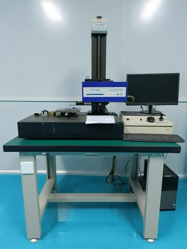
Taylor Hobson Form TalySurf surface profilometer in the Lensmind quality lab for lens surface metrology
Taylor Hobson Form TalySurf — surface profilometry in our quality lab
2D vision measuring machine inspecting a Lensmind lens component in the quality control lab
2D vision measuring machine — dimension inspection under 1 µm
Lens centering measurement with a Trioptics OptiCentric instrument at the Lensmind factory
Trioptics OptiCentric — lens centering & alignment measurement
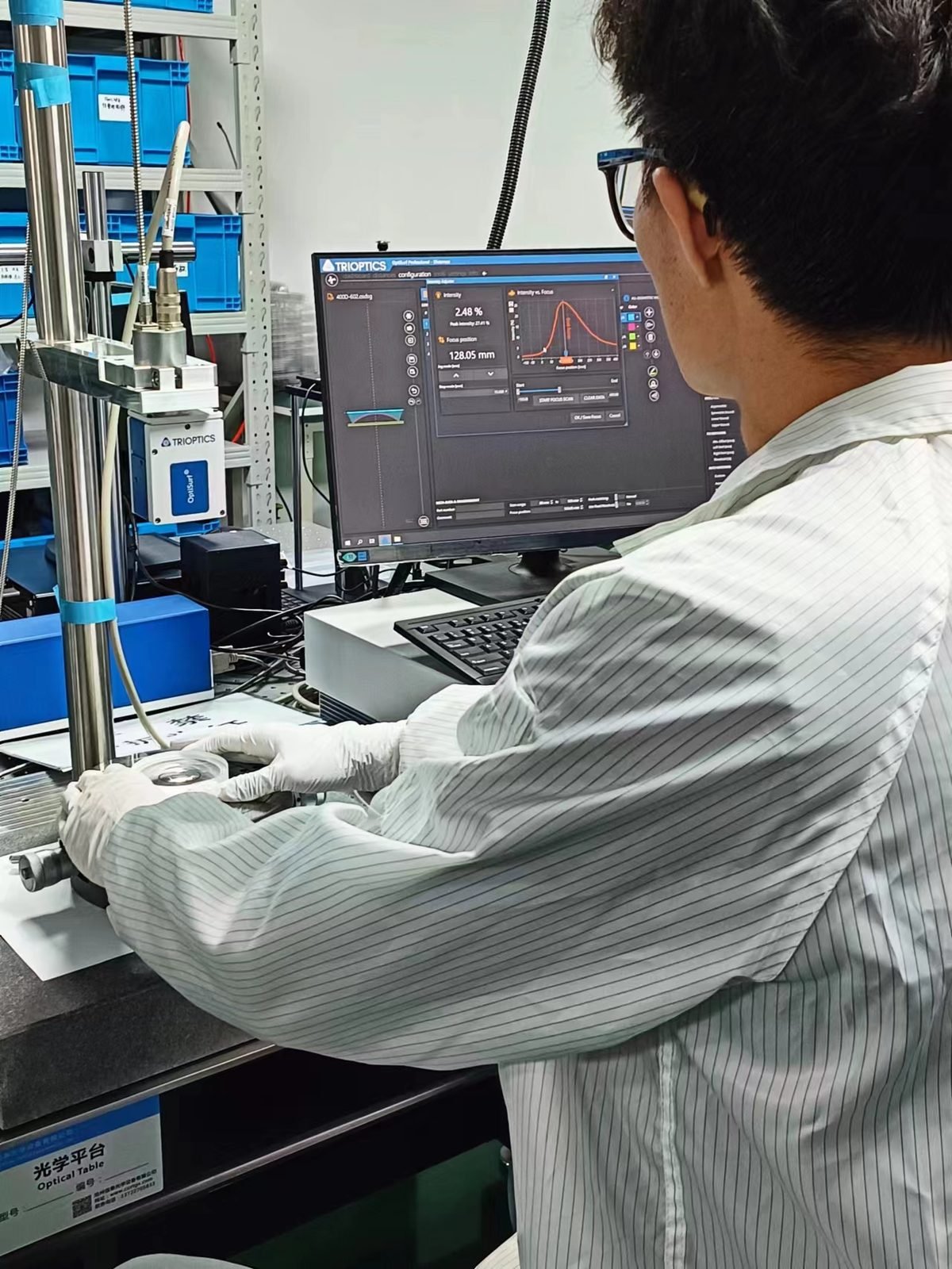
Focus position measurement of a Lensmind lens assembly with a Trioptics OptiSurf instrument
Trioptics OptiSurf — focus position measurement on the bench
Engineer running an MTF test on a Lensmind lens at a production test station
MTF test station — engineer running a production MTF test

Lab data & simulation records

MTF curves across image height for Lensmind machine vision lens configurations, sagittal and tangential
Measured MTF vs image height — sagittal & tangential
Relative distortion curve of a Lensmind lens plotted against image height in percent
Relative distortion curve, plotted per batch
Zemax through-focus MTF simulation of a Lensmind 54 degree f/1.2 lens design at 85 line pairs per millimeter
Through-focus MTF simulation @ 85 lp/mm
Zemax spot diagram of a Lensmind f/1.2 wide angle lens across 0 to 31.6 degree field positions
Spot diagram — F/1.2 wide-angle design, 0–31.6°
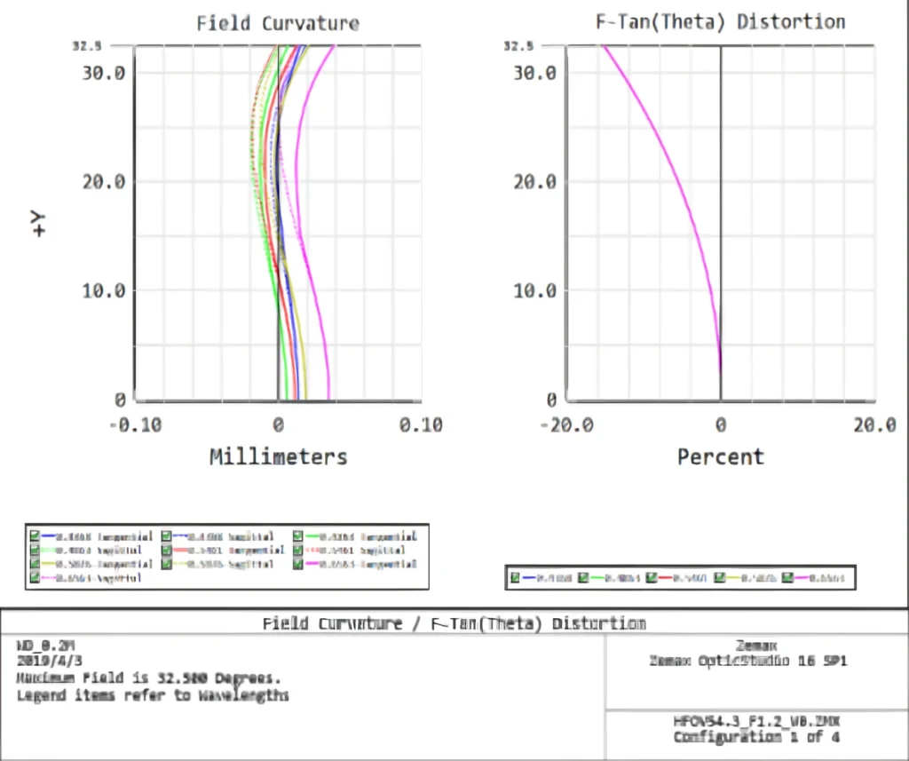
Field curvature and F-tan theta distortion plots from Zemax simulation of a Lensmind f/1.2 lens design
Field curvature & F-tan θ distortion — design analysis

Production floor

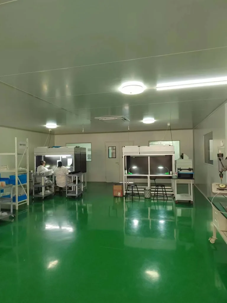
Operators assembling lenses inside a Lensmind cleanroom assembly room
Cleanroom assembly room — sub-2 mm optics built in controlled air
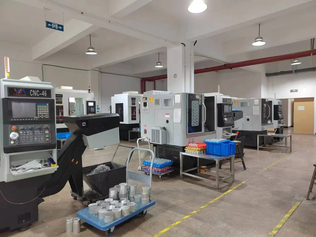
Row of CNC lathes machining precision lens barrels in the Lensmind workshop
CNC lathe workshop — precision lens barrels machined in-house
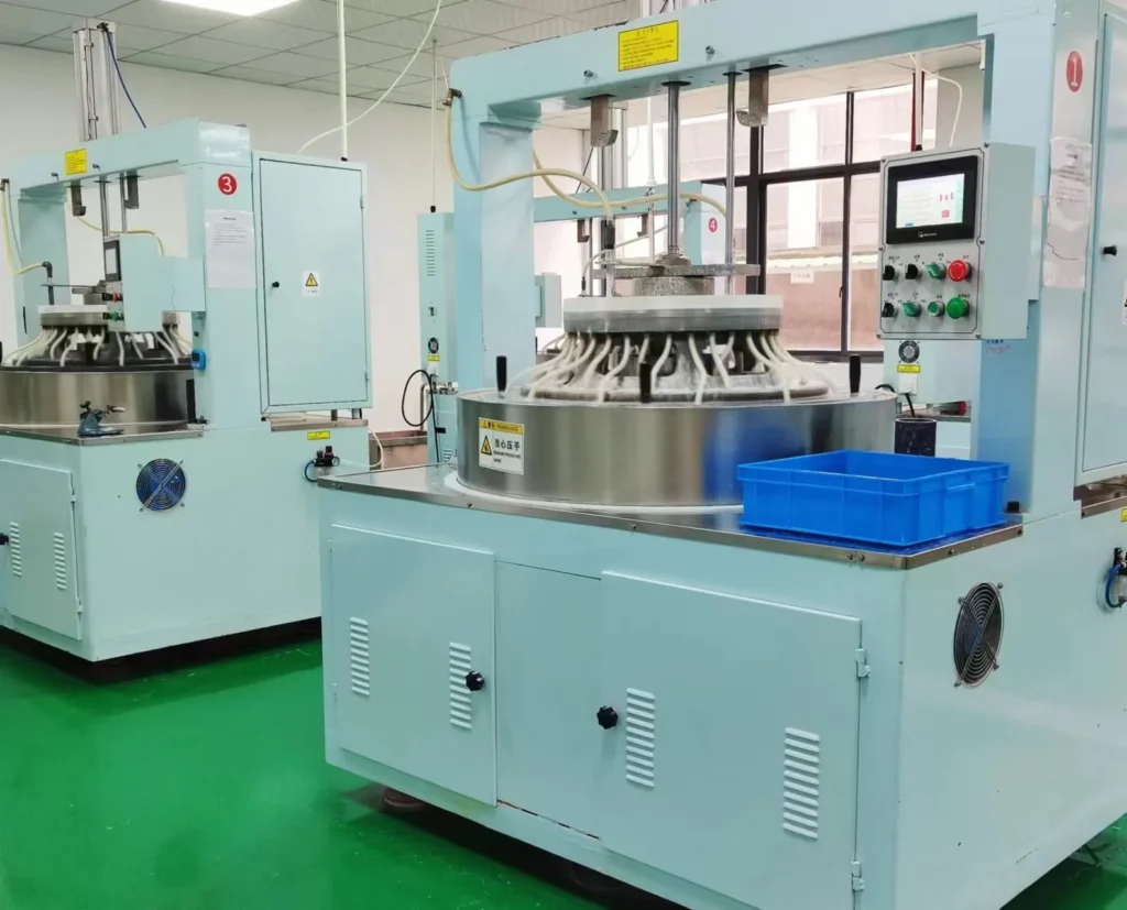
Optical polishing machines finishing lens elements at the Lensmind factory
Optical polishing machines — elements finished to curve
Ultrasonic cleaning and spin-dry line for optical parts at the Lensmind factory
Ultrasonic cleaning & spin-dry line for optical parts
MTF testing of M12 board lenses at a Lensmind production test station
M12 board lenses on the production MTF test station
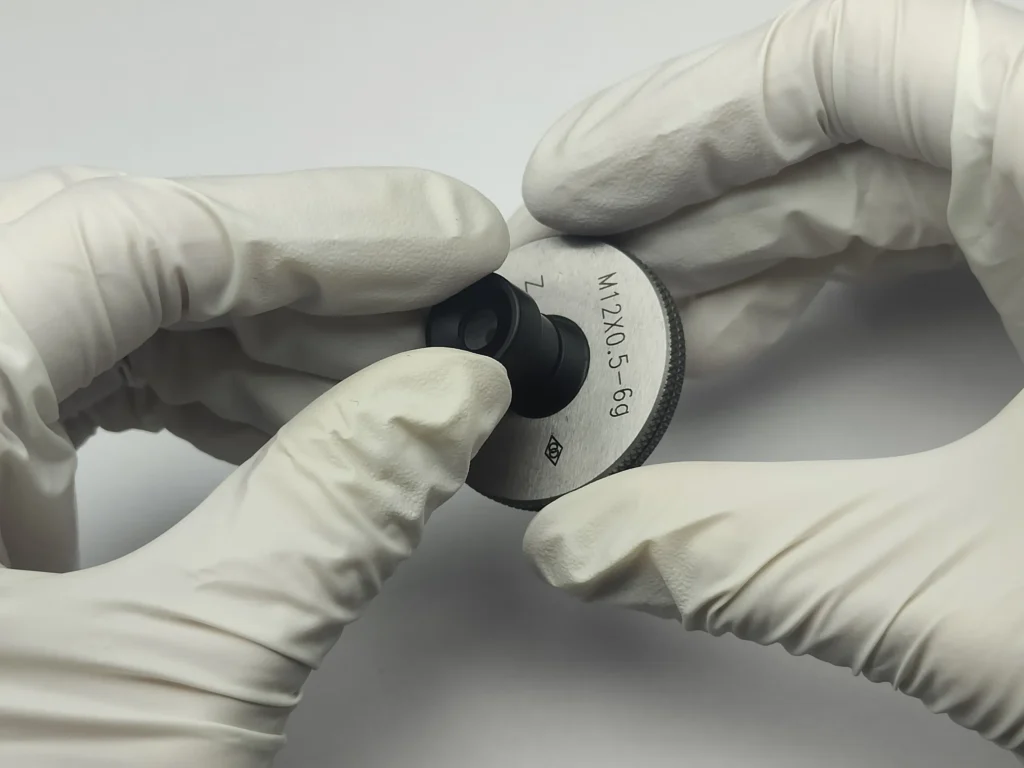
Checking M12x0.5 lens mount threads with a go thread gauge at Lensmind
M12×0.5 mount checked with a go thread gauge, every unit

Every batch ships with its own MTF, distortion, BFL and DOF records. Want the full test pack for a specific model? Request the full test report →