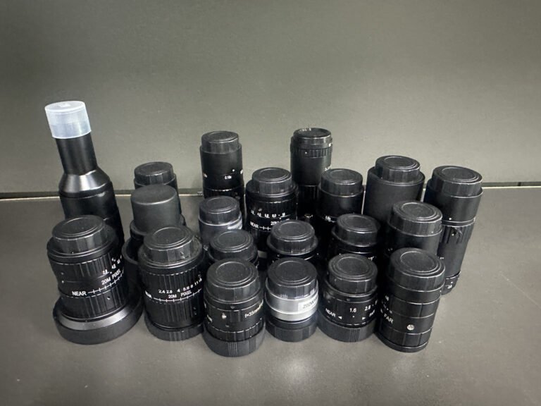
360° Panoramic Lens Family Guide: Pericentric, Catadioptric and Fisheye
One lens, one camera, the whole circumference: what pericentric panoramic optics do, where the fisheye boundary sits, and how side-wall builds are quoted.
read more…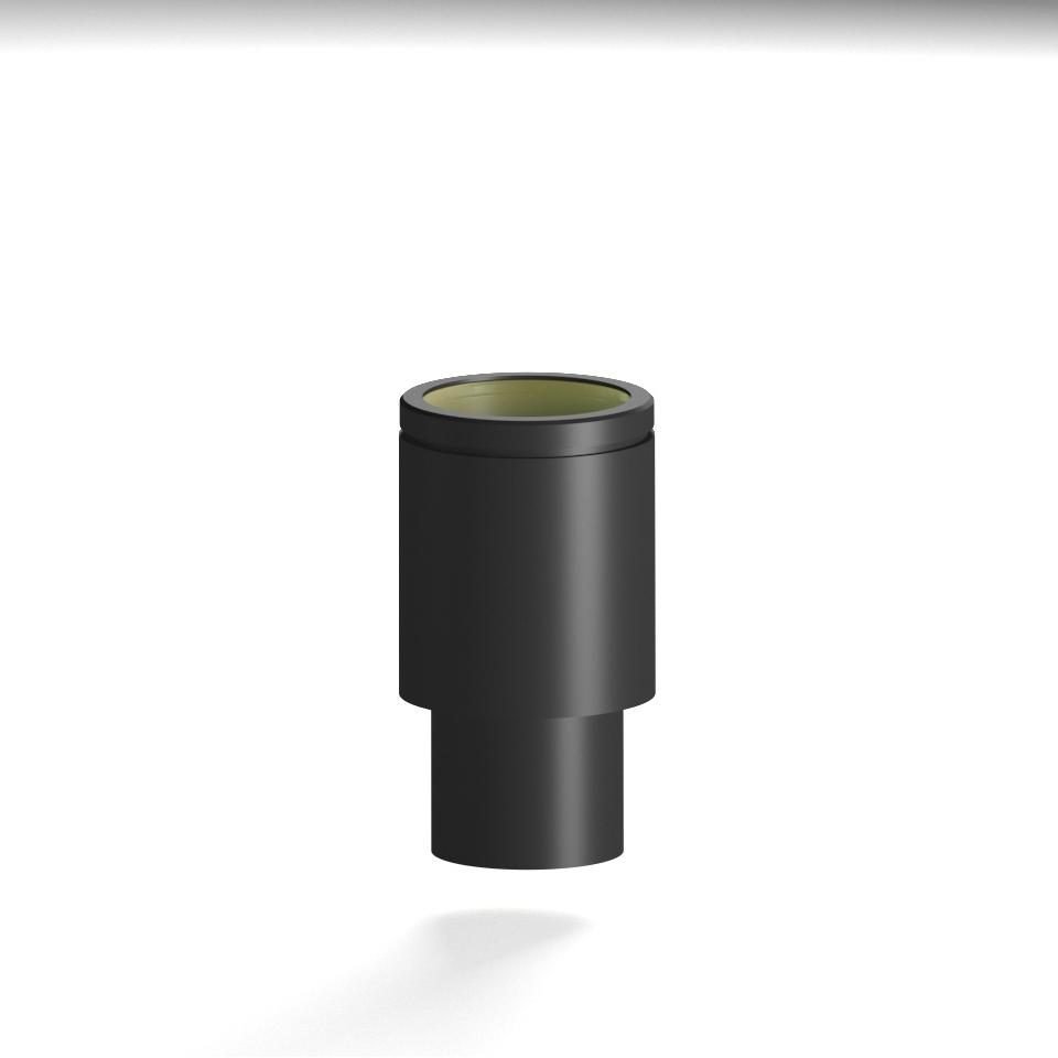
A stereo cell reports a pin height that drifts 40 micrometres between morning and afternoon. The calibration is fine. The software is fine. The two lenses are not a pair — they were pulled from the same catalog line, not matched to each other, and the difference between their distortion curves is being read as depth.
For paired-camera builds, the Lensmind machine vision lens catalog is the starting point for matched focal lengths in volume.
Key Takeaways
This family guide covers both halves of 3D imaging optics: the paired lenses that make stereo work, and the profiler optics that make laser triangulation work. If you are still at the family-selection stage, the five inputs in the machine vision lens selection guide point here once depth enters the requirement.

There is no lens that measures depth by itself. In passive stereo, two cameras look at the same scene from a known separation — the baseline. The system finds the same feature in both images and converts the pixel shift between the two views into distance.
That means the optical requirement is not about a single lens but about the relationship between two: stereo camera geometry assumes the two paths are equivalent, and any difference between them is indistinguishable from depth in the output.
Three relationships matter. Magnification has to agree, or the same object maps to different pixel counts in each view. The distortion curves have to agree, or a feature bends differently in each image. And the optical axes have to point the same way, or the useful overlap between views shifts off-centre.
Any of the three can be calibrated out on a bench and then drift back in service — with temperature, with vibration, with a lens that was removed and refitted during maintenance. Buying the match at the glass means the residual the calibration has to correct is small from the start.
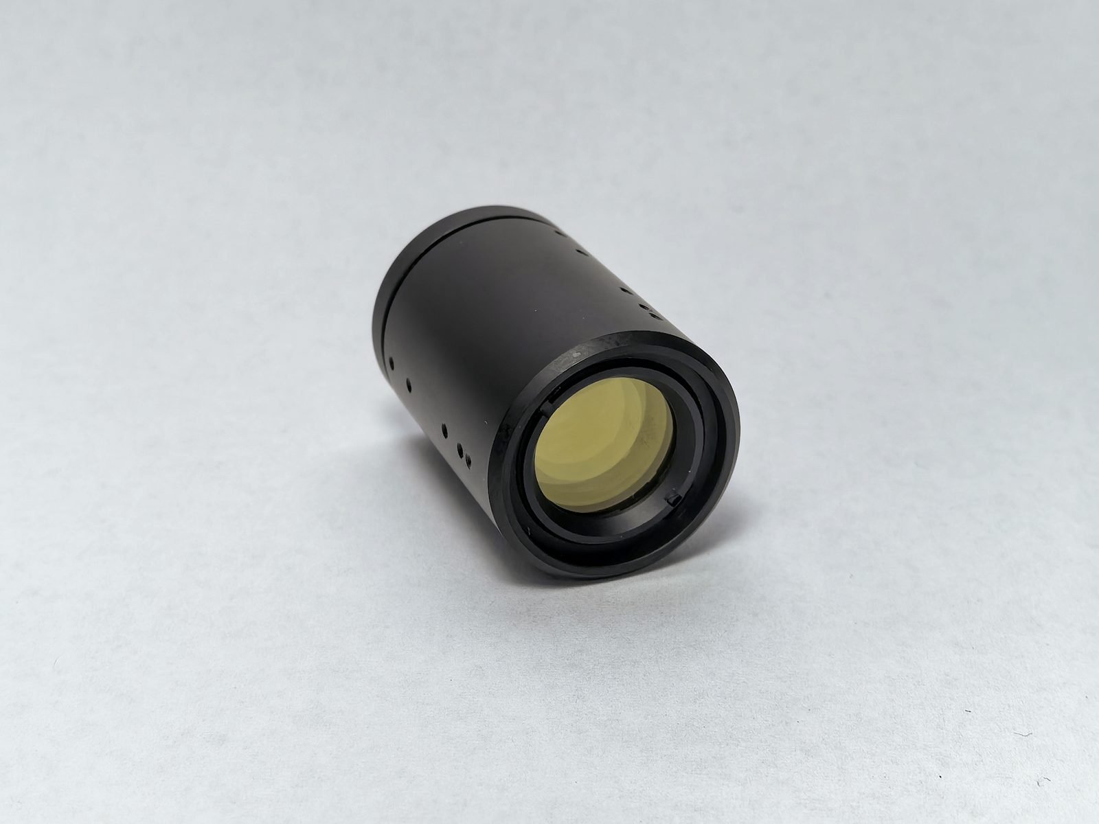
Stereo depth follows Z = f × B / d, where f is focal length, B is the baseline between cameras and d is the disparity — the pixel shift between the matched feature in the two views. Read the formula for its error behaviour and the procurement logic becomes obvious.
Disparity d sits in the denominator, which means depth resolution improves with focal length and baseline and degrades rapidly with working distance. The lens choice, not the algorithm, sets the ceiling on Z accuracy before a single image is captured.
Matching error enters the same equation. If one lens magnifies a feature by half a percent more than its partner, that difference appears as disparity, and disparity is depth. Over a two-metre working range, a residual that looks like a rounding error on the bench becomes a systematic height offset that no filter removes correctly.
The practical consequence: specify the match tolerance as a depth budget. Tell the factory what Z error you can tolerate at the far end of your working range, and the pair can be verified against that number rather than against an abstract optical tolerance.
| Purchase decision | What it controls | Where it shows up |
|---|---|---|
| Focal length and baseline | Depth resolution at working distance | Smallest height step the cell can resolve |
| Magnification match | Disparity offset between the two views | Systematic Z bias across the field |
| Distortion curve match | Feature correspondence across the field | Edge-of-field height errors |
| Axis alignment | Overlap and epipolar geometry | Usable field of view, calibration residual |
| Stop and coating match | Exposure and spectral consistency | Feature matching reliability |
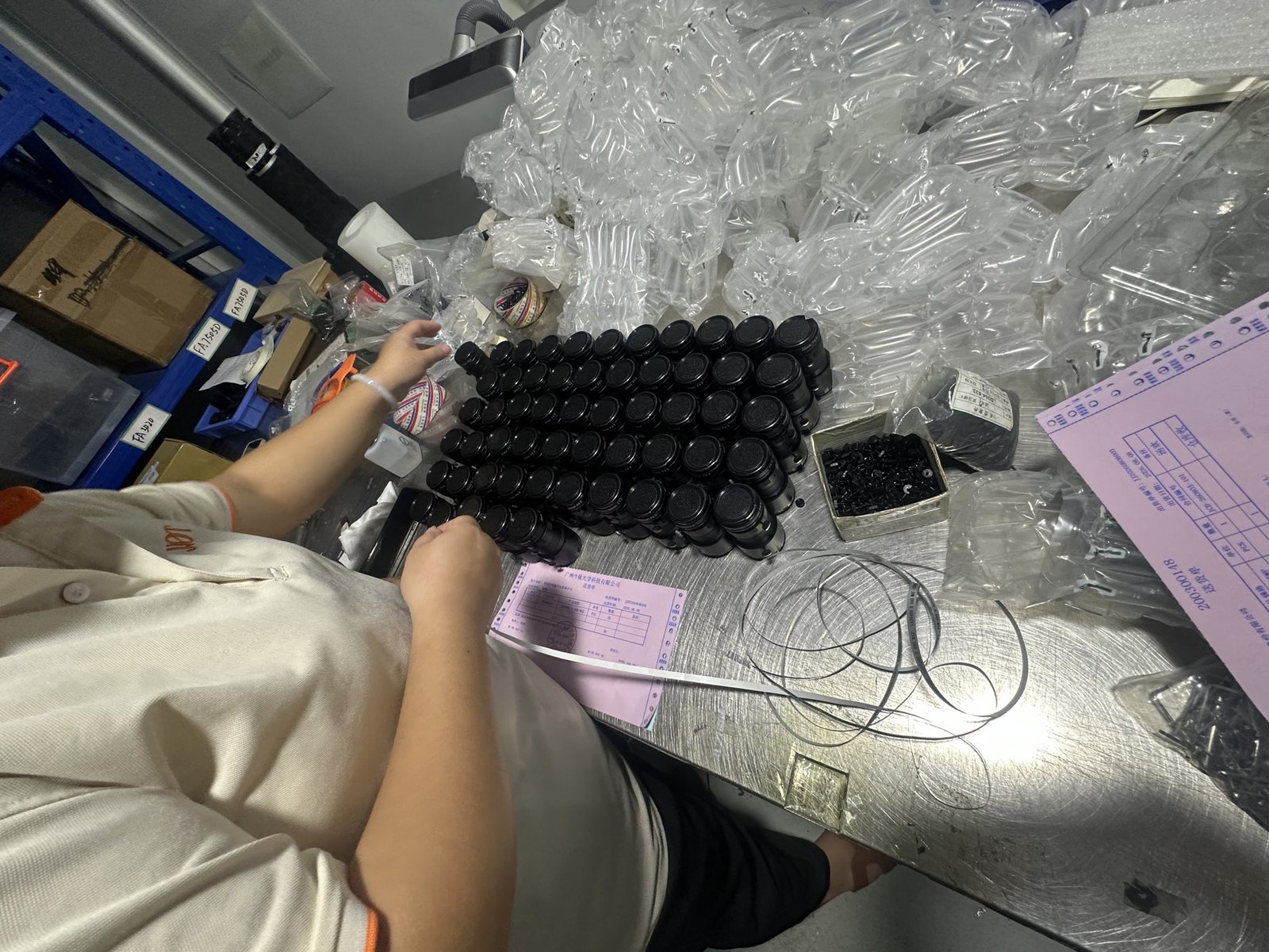
A matched pair is not two lenses of the same part number in one box. It is two barrels that have been measured against each other and released as a pair, with the measurement recorded against that pair’s serial numbers.
Lensmind verifies pairs on a Trioptics centration instrument for axis and centring, and on the MTF bench for imaging performance, and ships per-pair records with the order. The exact prescriptions are quoted per sensor and baseline — because a pair that is right for a 1/1.8" sensor at 300 mm baseline is not the pair for a 1" sensor at 1.2 m.
Two hardware families cover the common cases. The K3005A serves compact stereo stations where the cameras sit close together and the working range is short. The Q1356 covers wider baselines and longer working distances, which is where depth resolution usually needs the extra help.
Both are quoted as OEM programs rather than catalog rows, and they are listed on the 3D stereo vision optics page alongside the profiler hardware. Any supplier who does publish a ready-made 3D lens catalog should be asked which instrument the pairing was verified on.
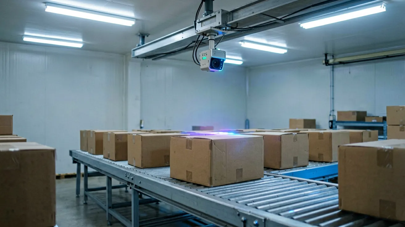
Two routes reach a height map, and they fail on different surfaces. Passive stereo recovers depth from disparity between two synchronized views. It needs texture or structure in the scene to match features, and it returns colour and a full-field map at once.
Active laser line scanning projects a line and triangulates it. It works on surfaces that carry no texture at all — polished metal being the standard example — and it produces dense, high-resolution height profiles along the line. It sees one line at a time, so the part or the scanner must move.
The decision usually follows the material. Coplanarity, pin geometry and general dimensional checks on textured assemblies go to stereo. Weld beads, untextured metal surfaces and profile measurements go to laser triangulation. Structured light is the third option when the scene is static and dense coverage matters more than cycle time.
Mixed lines are common, and they are not a contradiction: a single inspection cell can carry a stereo head for general presence and dimensional checks and a profiler for the welds. The optics are bought separately because the requirements are separate.
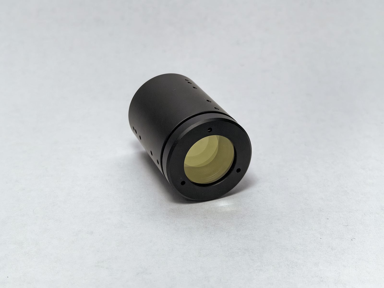
A profiler lens has one job: reproduce the projected laser line across the sensor at high contrast, across the whole measurement volume, at line-scan imaging quality. If the line smears at the edge of the volume, the height map loses resolution exactly where the part is tallest.
Two models cover the programs we see. The K2540A and K2569A are quoted against the sensor and the triangulation geometry (the angle between the projected line and the camera axis) because that geometry, not the lens alone, sets the measurement volume.
The optics behind them come off the same design and metrology line as the rest of the portfolio: MTF bench, distortion measurement and focus-position checks on Trioptics instruments, with the records travelling with the batch.
The common mistake at this stage is treating the profiler lens as a commodity barrel. A chevron-pattern projector and a 12K line sensor will both be blamed for line quality problems that originate in a lens chosen without reference to the triangulation angle.
Depth resolution is set by focal length and baseline. Line quality is set by the profiler optics. Neither is set by the software that reads them.
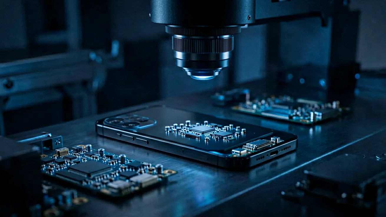
Three application groups account for most matched-pair and profiler programs. The first is geometric inspection of assemblies: coplanarity, pin height, connector seating and gap measurement, where a matched stereo pair gives symmetrical disparity across the field.
The second is surface work on untextured material. Weld beads, machined faces and castings are exactly where passive stereo struggles and a laser profiler earns its place, because the projected line supplies the texture that the material does not.
The third is logistics: parcel and pallet dimensioning, and bin picking. These use single-shot stereo over a large volume, and they often add a focus mechanism because the working distance range is wide. That is where an electrowetting depth of field adjustment — a liquid lens with no moving parts and a focus change in about 20 ms — replaces a mechanical focus stage.
The single-shot requirement deserves attention early. If the part cannot stop — a moving parcel, a robot picking from a bin — passive stereo or a single-shot structured-light pattern is the only route, because line scanning requires relative motion.
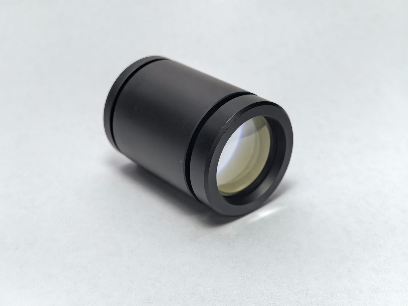
Five questions pick the route, and the answers are short. Is the surface textured or bare? Does the part stop, or does the measurement have to be single-shot? What baseline and working range does the mechanical envelope allow? What Z error can the application tolerate at the far end of that range? And is the task purely 3D, or does the same cell need colour and 2D inspection as well?
Send the sensor, the baseline, the working range and the Z target, and the first-pass recommendation — stereo pair or profiler, with the reasoning — comes back in the same 48-hour feasibility window the custom optics line runs on.
Where the program moves to volume, the same matched-pair procedure repeats per order, because a pair is a pair: the records from the original build describe serial numbers, not a part number. Repeat orders run on a 30-day cycle.
Nothing here needs an NDA to start. Optical prescriptions can stay on our side of the line; the buyer supplies geometry and targets, and receives a proposal that can be tested against a real part before tooling is committed.
If your cell already exists and the height data is drifting, the fastest diagnostic is a pair check: send the two lens serial numbers and the observed Z error over the working range, and the 3D optics team will say whether the pair matches the application or whether a matched replacement is the cheaper fix.
Yes. Depth error scales with matching error between the two views. When magnification, distortion and optical axis are matched at the factory, the residual after stereo calibration is smaller and stays smaller over temperature and vibration.
Passive stereo recovers depth from disparity between two synchronized views and suits textured scenes and single-shot requirements. Active laser line scanning projects a line and triangulates it, which suits untextured metal and dense height profiles.
Centring and optical axis on a Trioptics centration instrument, and imaging performance on the MTF bench. Both lenses are measured against each other and released as a pair, with per-pair records shipped.
They are standing hardware used in OEM stereo and profiler programs. Specifications are issued per pair against your sensor, baseline and working range rather than as a catalog datasheet family.
Yes, where the working distance range is wide. An electrowetting liquid lens changes focus in about 20 ms with no moving parts, which suits single-shot stereo over a large volume.
Feasibility first pass within 48 hours, prototype to mass production on a written 60-working-day commitment, and repeat orders at 30 days.

One lens, one camera, the whole circumference: what pericentric panoramic optics do, where the fisheye boundary sits, and how side-wall builds are quoted.
read more…
Eleven prism and planar-optics types on one line: how each is specified, what drives cost, and where 7-day sampling fits.
read more…
Four numbers pick the model: field of view, tube diameter, total track length and the matched sensor. The six catalog industrial models explained.
read more…