Lens Selection for Wafer Inspection: Telecentric Magnification and Metrology
Home - Lens Selection Guides - Lens Selection for Wafer Inspection: Telecentric Magnification and Metrology
Reading Time: 4 min ( Word Count: 1,039 )
A wafer review station measures the same feature twice and gets two different numbers. The stage is stable, the camera is the same camera, and the calibration was run that morning. What changed is the focus height: the part sat 40 µm lower on the second pass, and the lens was entocentric, so magnification moved with it.
Key Takeaways
Wafer inspection is a measurement problem, which is why magnification has to stay constant through focus — the property telecentric optics are built for.
Lensmind lists 24 telecentric models from 0.14X to 6X, in coaxial (TC), non-coaxial (TL) and bi-telecentric (BTC/BTL) types for 2/3-inch, 1-inch and 1.1-inch sensors.
Telecentricity and distortion are published per model: telecentricity typically under 0.1°, distortion from under 0.01% to about 0.07% depending on magnification.
Working distances cluster around 65 mm and 107–111 mm, which is a mechanical constraint on how the optics fit above a stage.
Selected models integrate an electrowetting liquid lens for about 20 ms focus response, which makes Z-stacking possible without moving the camera or the stage.
Buy the telecentricity and distortion records with the lens, not after a measurement dispute — they are per-batch test data.
This selection guide is written for yield- and metrology-adjacent work: wafer review, die inspection, bump and pad geometry, and any task where the same feature must measure the same at two different heights. The general five-input method is in the machine vision lens selection guide; what follows is what changes when depth enters the measurement.
Why Wafer Work Points at Telecentric Optics
A conventional lens images with perspective: closer objects appear larger. That is fine for presence detection and disqualifying for measurement, because the number a vision system extracts from a feature changes when the feature’s height changes by a few tens of microns.
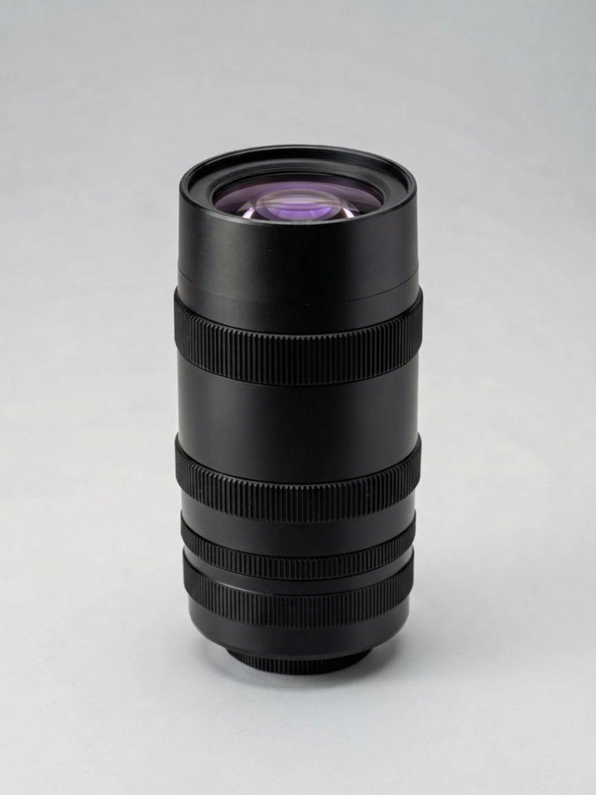
A telecentric lens removes that dependency. In an object-space telecentric design, the chief rays are parallel to the optical axis on the object side, so magnification stays constant over a depth range instead of varying with distance. That is the property that makes a measurement repeatable across a stack of wafers, a tilted die or a bowed substrate.
Bi-telecentric designs extend the same principle to the image side, which matters when the sensor is not perfectly positioned or when the assembly has to tolerate mechanical variation. Both types appear in the Lensmind telecentric sheet, alongside coaxial and non-coaxial illumination configurations.
The trade is size and working distance. Telecentric optics are larger than a comparable entocentric lens at the same field, and their working distance is fixed by the design — there is no zooming them closer. Planning the optics envelope before the stage is built is the difference between a clean integration and a redesign.
Magnification, Field and the Sensor Group
Telecentric lenses are specified by magnification rather than focal length, because the field of view is the sensor size divided by the magnification. That relationship makes the sensor choice first: pick the sensor, then pick the magnification that delivers the field you need.
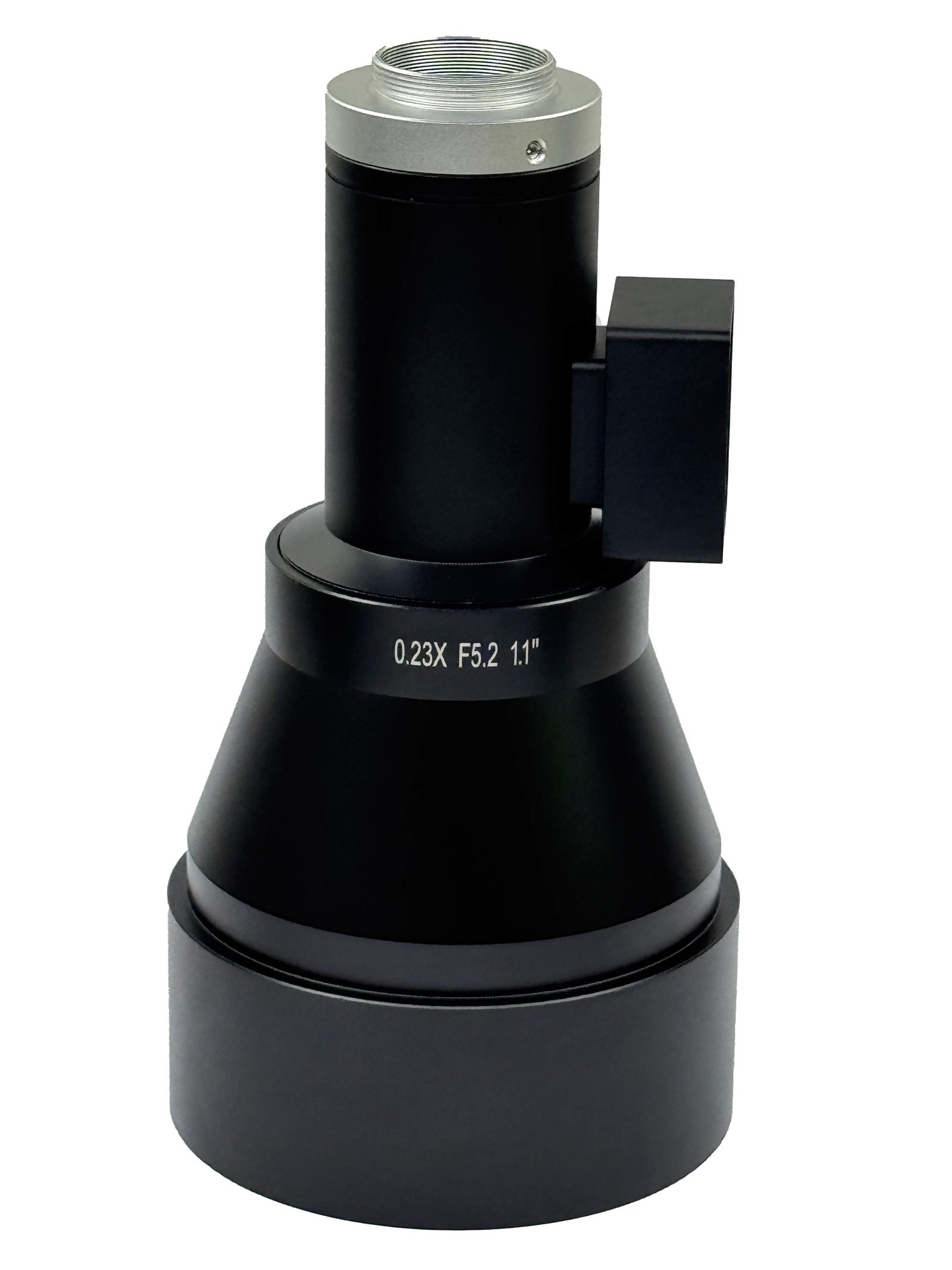
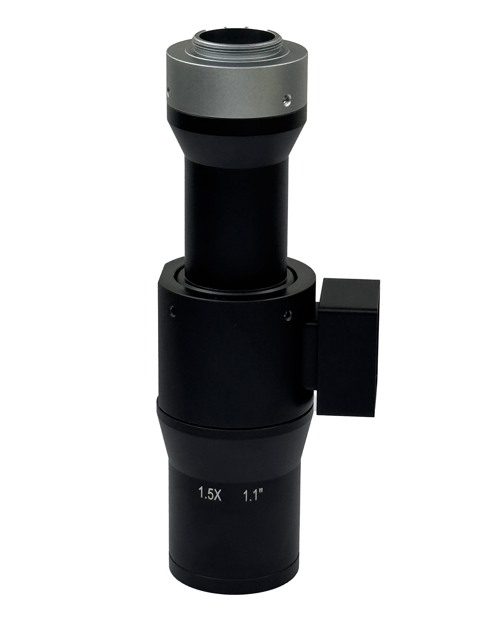
The Lensmind sheet covers 0.14X to 6X across 24 models, split by sensor format: eleven models for 2/3-inch sensors, two for 1-inch and eleven for 1.1-inch. A 1.1-inch sensor at 0.8X gives a 17.5 × 12.8 mm field; the same sensor at 3X gives 4.7 × 3.4 mm. Both are catalog models, and the choice between them is decided by what the station has to see.
Resolution per pixel follows the same arithmetic. When magnification rises, each pixel covers less of the part, so a feature that occupies ten pixels at 1X occupies thirty at 3X. For defect review that is the entire point; for full-wafer mapping it is a throughput problem, which is why many stations run a low-magnification overview and a high-magnification review objective rather than one compromise lens.
The working distance is the third number in the same decision. Most models sit at 65 mm or around 107–111 mm, which is a real spacing requirement above the wafer surface, not a preference.
Magnification
Sensor
Object field
Working distance
Typical distortion
0.8X (TC0.8X110N1.1)
1.1"
17.5 × 12.8 mm
110 mm
<0.02%
1.0X (TC1X110N1.1)
1.1"
14.2 × 10.4 mm
110 mm
<0.05%
1.5X (TC1.5X110N1.1)
1.1"
9.5 × 6.9 mm
110 mm
<0.05%
3.0X (TC3X65N1.1-GL)
1.1"
4.7 × 3.4 mm
65 mm
<0.05%
1.0X (TC1X110N23)
2/3"
8.8 × 6.4 mm
110.9 mm
<0.05%
Telecentricity and Distortion: Reading the Numbers
Two published figures decide whether a telecentric lens is good enough for a given measurement. Telecentricity is the angular error of the chief rays, quoted in degrees and typically under 0.1° across the sheet, with a few models at or under 0.2°. It describes how much magnification still changes with height, in the residual sense.
Distortion is the second figure and it is quoted per model rather than as a family average: values run from under 0.01% on some 2/3-inch models to about 0.07% at the largest magnifications. For a station measuring a 100 µm feature, a 0.05% distortion figure is a 0.05 µm error at the edge of the field — small in absolute terms, and worth knowing rather than assuming.
Both numbers are best understood against the classic aberration vocabulary. Distortion is the geometric error that bends straight lines, and field curvature is the reason an edge feature can be out of focus while the centre is sharp. In a telecentric system these are pushed down by design, and the published figures say how far down. The full per-model table, including the coaxial and non-coaxial configurations, sits on the telecentric lens page.
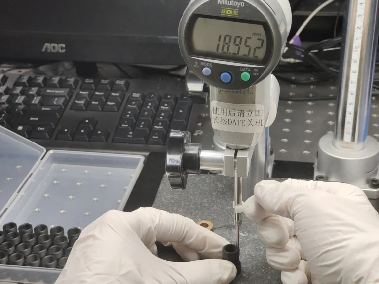
The verification expectation is straightforward: per-batch telecentricity and distortion records against the design, available with the shipment. A supplier that publishes a family-wide distortion number for a measurement family is describing an average, not the part in the box.
HANGZHOU FACTORY · ISO 9001
Measuring features that sit at different heights?
Send the sensor, the smallest feature you measure and the height range it appears over. The telecentric optics team returns magnification, working distance and the published telecentricity and distortion figures for the models that fit, with per-batch test records.
24 models 0.14X-6XTelecentricity <0.1°20 ms liquid focus
Liquid Focus and Z-Stacking Without Moving the Stage
A wafer review station usually wants several focal planes: one for the surface pattern, one slightly above for particles, one below for layers. Moving the stage or the camera between planes costs time and introduces mechanical error.
Selected telecentric models integrate an electrowetting liquid lens, which changes focus in about 20 ms with no moving parts. That makes multi-frame Z-stacking practical inside the cycle time, with the magnification still held constant by the telecentric design rather than by the focus mechanism.
The combination matters for measurement integrity. A focus mechanism that changes magnification as it moves would reintroduce exactly the error telecentricity removed; the liquid lens shifts focus without touching magnification, so the two techniques reinforce rather than fight each other.
Where the station already has a Z axis, the liquid lens is optional. Where the objective sits inside a fixed envelope — common on review tools with limited headroom — it is often the only way to get multiple planes without redesigning the head.
Integration Details That Decide the Station
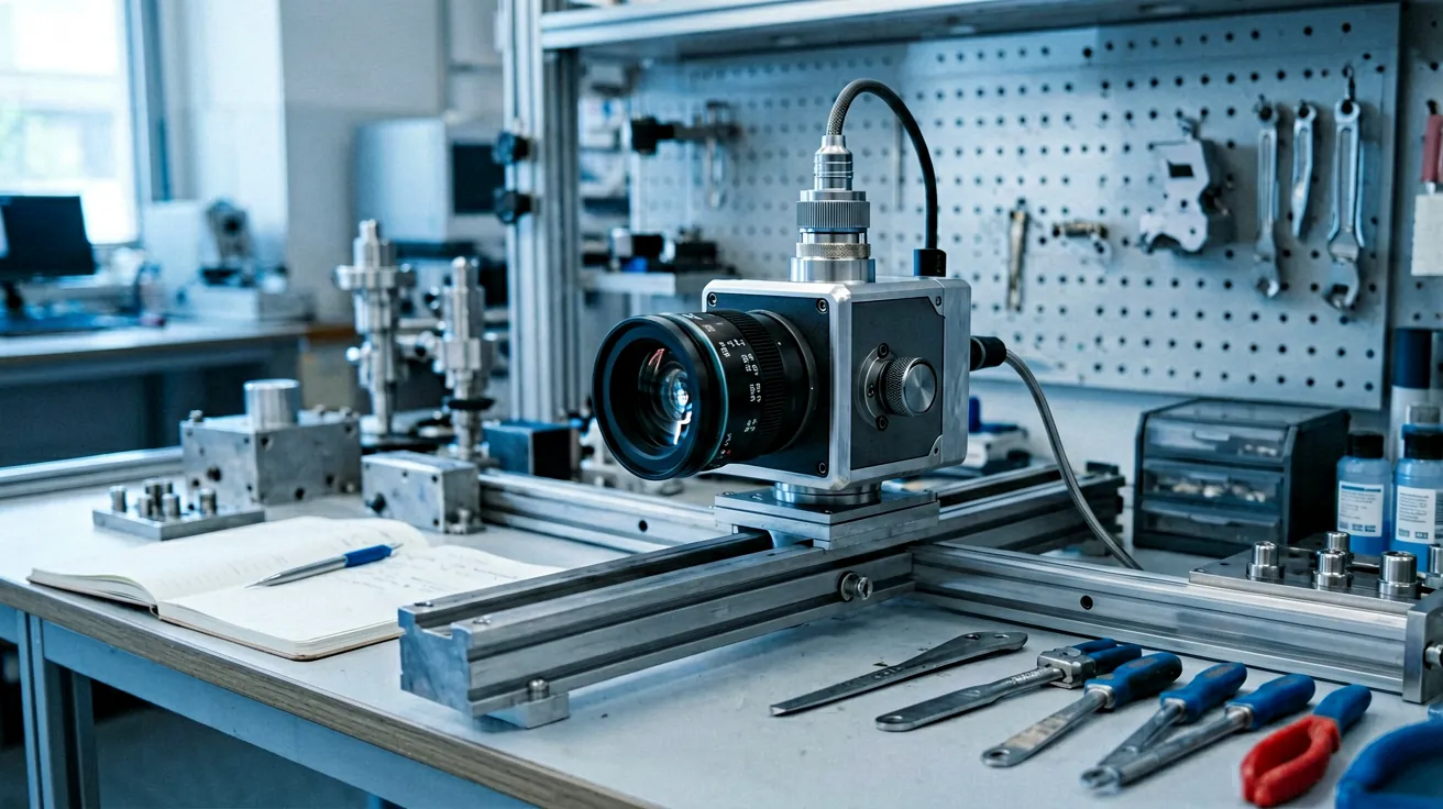
Telecentric lenses are mounted by their barrel and their working distance, so the mechanical design has to hold alignment over temperature. A station that clamps the objective loosely will drift out of the depth of field before it drifts out of line, which appears as intermittent focus rather than as a gross misalignment.
Illumination is the second integration decision. Coaxial and non-coaxial versions of the same magnification exist because different surfaces respond differently: a reflective wafer surface often wants coaxial light returning along the optical axis, while a matte or coated surface may want oblique light instead. Choosing the illumination type at the same time as the lens avoids a rebuild.
The third is the sensor match. The 2/3-inch, 1-inch and 1.1-inch groupings on the sheet exist because image circle and magnification are tied; a lens built for a 2/3-inch sensor will not cover a 1.1-inch sensor at the same magnification, and the field it delivers would be wrong even if it did.
For lines moving from development to production, the practical sequence is a proof-of-principle measurement on a candidate model, then a specification freeze with the test records attached. The custom optics route handles the cases the 24 catalog models do not cover.
Conclusion
Telecentric optics hold magnification constant through focus, which is what makes measurement repeatable across height variation.
Twenty-four catalog models span 0.14X to 6X on 2/3-inch, 1-inch and 1.1-inch sensors, in coaxial, non-coaxial and bi-telecentric types.
Telecentricity (typically under 0.1°) and distortion (under 0.01% to about 0.07%) are published per model and verified per batch.
Liquid-lens focus on selected models adds about 20 ms Z-stacking without moving the stage or disturbing magnification.
If the review station already exists and two passes disagree, the most useful data is the height difference between the passes and the magnification in use: from those two numbers it is usually possible to say whether the residual error is telecentricity, distortion or something mechanical in the head.
Frequently Asked Questions
When do I need a telecentric lens instead of a normal FA lens?
When measured dimensions must not change with depth or object position — wafer review, bump geometry, thickness work and any measurement where the part sits at varying height.
What magnification range is available?
0.14X to 6X across 24 catalog models, with sensor groupings for 2/3-inch, 1-inch and 1.1-inch cameras.
How is telecentricity specified?
As an angular error, typically under 0.1° on most models and under 0.2° on the largest magnifications, verified per batch against design.
Can a telecentric lens autofocus?
Selected models integrate an electrowetting liquid lens that changes focus in about 20 ms with no moving parts, which supports multi-frame Z-stacking.
What working distances are available?
Most models sit at 65 mm or around 107 to 111 mm, which is a mechanical constraint to plan for above the stage.
Does the same model work for 2/3-inch and 1.1-inch sensors?
No. Image circle and magnification are tied to the sensor group, and the sheet separates 2/3-inch, 1-inch and 1.1-inch models for that reason.
Baker Zhao
Founder, Lensmind Optics
Baker Zhao is the founder of Lensmind Optics, with 26 years of experience in the optical industry — including Vice President of Sales at Sunny Optical (Zhongshan) and earlier roles at Foxconn, LG and Sintai Optical. He leads Lensmind with a mission to help customers find reliable, application-specific optical solutions from development to volume production.
A short-working-distance large-FOV feasibility input pack is the maker-ready file that states part size, stand-off, pixel budget, and which image costs the buyer will...
Turning a 50 micrometre defect at 200 millimetres into a lens commitment means locking pixel pitch, image height, and a verification target before anyone...