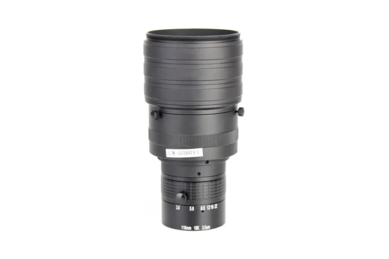
You cannot assign blame from the symptom, and no number of remounts will produce the answer. A lens that binds in one body and slides in another is most often a conforming lens mated to a conforming body near the opposite ends of their allowed sizes, which means the shop and the maker can both be right and the fit can still be wrong. What ends the argument is not another mating trial but an independent check of each part against the thread callout on its own drawing, using a calibrated GO and NOT-GO pair: a ring gauge for the lens male thread and a plug gauge for the body female thread, both cut to the same nominal size, pitch, thread form and tolerance class as the drawing. When each part passes its own gauge, the dispute moves to alignment, seating, damaged threads and adapters. When one part fails, the argument is over.
If you are comparing suppliers for this kind of optic, the Lensmind machine vision lens catalog is the hub for our standard models and custom options.
Why a Binding Thread Can Still Be an In-Tolerance Thread
Thread tolerance classes are one-sided allowances, not a target with equal error on both sides. An external thread at the large end of its class and an internal thread at the small end of its class will interfere when assembled, even though both parts are fully conforming. Reverse the pairing and the same lens drops into the same nominal body with visible free play. That is why the complaint “it binds in some bodies and slides in others” describes a stack of two distributions rather than a defective component, and why swapping lenses between bodies until something sticks proves nothing at all.
The sample size deserves to be said out loud. Three bodies and one lens is not a test, and neither is twelve remounts of the same pair. Before any conclusion is drawn, build a small matrix: three or four lenses against three or four bodies, with the result for every combination recorded, and the service history of each part noted. A row or a column that fails everywhere points at a part. A checkerboard pattern points at the tolerance stack. Scattered single failures point at damage or contamination. This costs an afternoon and it decides whether the next conversation is with the maker or with your own assembly bench.
Remounting is itself a cause of binding. Cross-threading on the first turn removes material from the flank, trapped chips hold the two parts apart, and repeated hand tightening on an anodized aluminium body can gall the thread surface. None of that appears on a drawing, and none of it is a dimensional error in the part as manufactured. Clean the threads, inspect them under magnification, and record the condition before gauging. A thread that passes its gauge after cleaning was contaminated, not out of tolerance, and the maker should never see that part in a dispute file.
Include every adapter in the stack as well. A ring that lifts a CS-mount camera to the C-mount flange distance, a step ring, a filter ring or a microscope adapter is a third part with a thread at each end, and it is usually the one component that appears in nobody’s drawing. Gauge the adapters before you call the maker, because a single nonconforming adapter reproduces the exact symptom that started the argument. The mount guidance published on this site already gives the two flange distances side by side, 17.526 mm for C-mount against 12.5 mm for CS-mount, with a 5 mm adapter ring doing the conversion, and a dispute file should treat that ring as a threaded component with a class of its own.
What the Drawing Has to State Before Anyone Measures
A thread callout is a size, a pitch, a thread form, a tolerance class and the gauge standard that defines that class. “M12 mount” and “C-mount” are not callouts. If the drawing and the purchase order do not name the class, the argument is not about threads yet, it is about a missing requirement, and no gauge reading can settle it because there is no limit to compare the reading against. Fix the document first, then measure.
Two class systems commonly meet in one workshop and they do not convert into each other. Metric threads are called out with classes such as 6g for the external member and 6H for the internal member, while Unified inch threads use 1A, 2A and 3A for external and 1B, 2B and 3B for internal, with 2A and 2B as the usual commercial pairing. A C-mount body carries an inch thread, called out as 1.000-32 UN, with class 2A on the lens side and 2B on the camera side in most commercial specifications. An M12 S-mount lens carries a metric thread at 0.5 mm pitch, checked against an external class such as 6g in a ring gauge cut to that size and pitch. Where an adapter joins the two families, the class has to be stated separately on each side of that adapter.
Pitch is the second trap. The same nominal diameter exists in more than one pitch, and two threads of equal diameter but different pitch look alike in a photograph and share nothing in a gauge. A ring gauge cut for one pitch will not check the other at all, and forcing a fine pitch into a coarse body produces permanent damage that no tolerance band can explain afterwards. Read the pitch from the drawing or from a pitch gauge before ordering inspection equipment, and write both numbers on the inspection sheet.
Engagement length matters more than most shops expect. A gauge should be made for the same thread length as the part it will mate with, because pitch error and taper accumulate along the engaged length. A short ring gauge will run onto a lens thread that binds at full depth in a deeper body, and a short plug gauge will pass a body whose thread tightens only in its last turns. Ask the gauge maker for the gauge thread length and compare it with the engagement in the real assembly before you trust a pass.
Surface treatment changes which part has to pass. An anodized or plated thread measures differently from the bare machined blank, and the tolerance class applies to the delivered part. Gauge the finished item, not the pre-treatment sample. Otherwise a body that passed inspection in the machine shop can be out of class by the time it reaches assembly, and both records will be honest and still disagree.
The Gauge Pair That Ends the Argument
The lens carries an external thread, so it is checked with a thread ring gauge. The camera body carries an internal thread, so it is checked with a thread plug gauge. Each is supplied as a GO and NOT-GO pair, and each pair must be made for the exact nominal diameter, pitch, thread form, tolerance class and engagement length named on the drawing. There is no universal gauge and no “close enough” class, and a gauge cut for a neighbouring tolerance is not an arbiter. The gauging discipline itself is written down: ISO 1502 covers metric screw thread gauges and gauging, and ASME B1.2 covers the Unified inch equivalents. Name the standard in the dispute file, because “the gauge says so” is weaker than “the gauge, made to this standard and calibrated to this certificate, says so”.

The logic of the pair is what makes the result usable by both sides. The GO member is cut to the worst-case mating part at its maximum material condition, so a part that accepts GO can be assembled with any conforming counterpart. The NOT-GO member is cut to the minimum material limit of the thread being inspected, so a part that refuses NOT-GO has not fallen below its own lower limit. Passing both checks bounds the thread from two directions and produces a statement that does not depend on opinion: this part, as delivered, is inside the class on the drawing. That is also why a mating trial against the other party’s parts never settles anything, since it tests the combination rather than either part.
Acceptance practice is strict about how the gauges are used, and a disputed result is usually a disputed method. The GO gauge should enter the full specified engagement by hand, without tools and without force. The NOT-GO gauge should not enter beyond the amount the drawing or the gauge standard permits, which is given as a small number of turns, not as “a little”. Sizes are defined at the reference temperature, so a part straight off a warm machine and a part that has sat in a cold inspection room are not being compared under the same conditions. Threads have to be clean and free of burrs, because a chip in the flank will stop a conforming GO gauge and create a failure that exists only on the bench.
The gauges themselves have to be in calibration, and this is where a shop quietly loses its case. A worn GO ring gauge runs onto an undersized lens and certifies it, which reproduces the exact failure pattern you are trying to diagnose: inspection agrees with the bad parts and assembly still binds. Record the gauge identity, its certificate number and its calibration due date on every result, and confirm the members against setting plugs. A pass or fail judgement without a gauge identity is an opinion with a stamp on it, and a maker’s quality engineer is entitled to say so.
If the dispute survives a gauge result, move to numbers. The controlling fit dimension is pitch diameter, measured on the external thread by the three-wire method or on a thread measuring system, and on the internal thread with a certified thread plug, an indicating gauge or a coordinate measuring machine. Add the major diameter of the male thread, the minor diameter of the female thread, pitch and flank angle, taper, lead error, runout, and the squareness and location of the seating shoulder. A caliper across the outside diameter, reading something close to nominal, carries almost no information, because the nominal diameter can be correct while pitch diameter, flank angle or runout makes the pair bind.
How to Read the Four Results
The gauge pair produces four outcomes, and each one points somewhere different.
- The lens fails its GO ring. The male thread is too large, tapered, burred or misaligned. The lens is the nonconforming part, and it will show up in every body it enters, including the ones that felt acceptable.
- The lens accepts GO and also accepts NOT-GO. Pitch diameter is under the lower limit, so the thread is loose. That is still a lens condition, and the maker still owns the document.
- The body fails its GO plug. The internal thread is too small, damaged or contaminated. Read the service history before blaming the maker, because an impact or a forced assembly gives the same reading as a manufacturing error.
- The body accepts GO and also accepts NOT-GO. The internal thread is oversize, which is loose at best and a stripping risk at worst in a mount that is tightened repeatedly during servicing.
When all four checks pass and the assembly still binds, thread size is not the cause, and the argument should stop there. Inspect axis alignment, runout, burrs on the first thread, debris and interference at the shoulder or seating face. A thread gauge proves functional size, and it says nothing about alignment or register, so a pair of parts that are each in class can still be assembled badly. This outcome is also the one that usually ends a shop-against-maker dispute without a winner, because after both parties have passed their own drawings, the remaining causes are assembly practice and handling damage, and those belong to whoever touched the parts last.
A Record the Maker Will Sign
The gauge result is worth exactly as much as the paper it arrives on. A usable record carries the part number and serial or batch, the drawing revision, the thread callout in full, the gauge identity with its calibration certificate number and due date, the GO result, the NOT-GO result including how far it entered, the cleaning state of the part, the measurement temperature if numbers were taken, the inspector and the date, and an explicit disposition for the part. Add a photograph of the thread under magnification, and keep the part itself, because a rejected sample that has been returned is a rejected sample that cannot be re-inspected.
The arbitration rule fits in one sentence and both sides can sign it in advance: the part that fails its own gauge against its own drawing is the nonconforming part. Mating trials, customer complaints and shop-floor opinion are not substitutes. This is the same discipline that makes a calibration certificate worth reading, since a certificate that names the gauge, the reference and the date is what turns a pass stamp into evidence. It is also why the drawing has to be frozen before production instead of edited after the first complaint, which is the point of the first-article gate that locks the drawing.
Ask the maker for its own side of the record rather than a summary. A thread inspection result belongs in the batch pack that already travels with a lens order. Every production batch from the Lensmind factory in Hangzhou ships with test documentation covering the agreed family parameters, typically MTF, distortion, back focal length and depth of field, together with the batch number, the test conditions, the inspection coverage and an explicit pass or fail judgement, and those reports are normal output rather than a special request. A mount thread result fits on the same page. Barrels are machined in house, and final metrology is part of the production sequence, so a thread check on a mount is dimensional work the process already supports. ISO 9001 is the only certification the company claims, and a certificate is a system claim rather than a thread measurement, which is exactly why the measurement itself has to be asked for by name.
Write the Thread Clause Into the Next Order
The cheapest place to end this argument is in the purchase specification, before the first part is cut. Name the nominal diameter, the pitch, the thread form, the tolerance class on each side of the joint, the gauge standard that defines the class, the engagement length, and the acceptance method. State that the delivered, finished part is what gets gauged. Name the adapter rings with the same callout, because they are part of the assembly and they fail in the field like any other thread.
Then agree on the gauge before there is a dispute. Agree which gauge family will be used, whether the shop and the maker will gauge with the same instrument or with correlated pairs, and what result counts as conforming. The wider class system is documented in the ISO metric screw thread standard, and a clause that cites the standard is easier to enforce than one that quotes a nominal size. For M12 mounts, the metric class system applies directly; for inch mount threads the equivalent Unified classes apply, and both belong on the drawing rather than in a conversation.
Two small commitments complete the clause. First, incoming inspection: every batch of bodies and adapters is gauged against the same class as the lens, so a failure is caught before the parts meet on the bench. Second, sample retention: hold one rejected part and one accepted part from each disputed lot, with the record attached, until the issue is closed. A shop that can produce a calibrated gauge result, a clean part and a photograph stops arguing about blame and starts arguing about the drawing, which is the only argument that produces a corrected part.