LED Flicker After Power Supply Swap: Lighting Specs That Match Camera Exposure
LED flicker after a power supply swap is an electrical-to-exposure matching miss. Lock lighting electrical specs to the camera exposure plan before the next...
read more…
Image tilt along the scan direction is a focus gradient, not a rotated picture. The two ends of the scan line reach best focus at different object distances, so one end of every line runs soft while the centre stays sharp. A 0.4 mm focus difference across a 57 mm line is a 0.7% slope, and a 0.7% slope is 0.40°. Three causes produce the gradient: a lens body pitching under its own overhang, an adapter face that is not square to the sensor, and a tilted target. According to ISO 10110-5:2026, surface form is stated in nanometres, so a 0.1 mm mechanical question cannot be settled with a 100 nm optical argument. The slope is the number that matters.
Image tilt along the scan direction appears as two signatures, and a bench has to name which one is present. A focus gradient means the focal surface is pitched against the sensor row. Both ends of the line blur by a similar amount while the centre stays sharp. A roll means the lens or the camera is rotated about the optical axis. Straight vertical edges lean, and the lean grows from one end of the line to the other. A 16K line holds 16,384 pixels, and a 3.5 µm pitch makes the line 57.3 mm long. For example, 0.1° of roll moves each end by about 50 µm, which is 14 pixels or 0.09% of the line. A gradient of the same 0.1° is a 0.17% slope and stays invisible on a printed chart. According to ISO 9335:2025, an image number travels only with its measurement conditions. Design-stage budget sits in the sensor tilt and decenter limits note; the field measurement is a separate job.
A long adapter turns a line-scan lens into a cantilever. The barrel has mass, the centre of gravity sits ahead of the flange, and the adapter pushes the flange further from the camera. The bending moment at the first joint is mass times the horizontal distance from the clamp. Compliance in the adapter, the flange face and the clamp adds to the deflection. A 40 mm 16K class body is long enough for sag to show across a 57 mm line. In practice the front thread is an optical reference, not a load path, and a bracket on the front barrel only moves the problem. With the band at the centre of gravity the clamp carries 100% of the moment, and a 0.7% slope in the image is the symptom. According to ISO 10110-5:2026, flange flatness is a surface form callout, so the value belongs on the drawing. Catalog pages for the line-scan family list focal length and image circle, not stiffness.
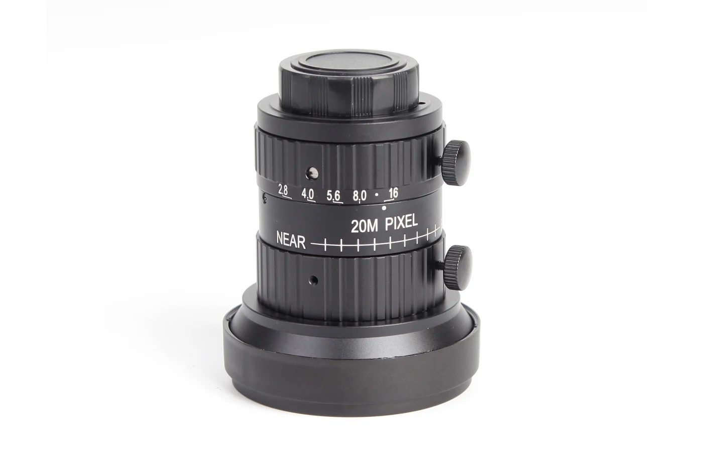
Three bench steps separate the gradient into an owner, and each step answers a different question. First, sweep a dial indicator around the adapter face while the camera turns. Runout at the flange seat is a face error, and 0.02 mm across a 57 mm flange is a 0.035% slope. Second, fit a known-good lens of the same model. When the soft end follows the new barrel, the lens owns the gradient. Third, clock the barrel through 180° where the mount allows. A flipping soft end points at the lens flange, while a soft end staying on the same image side points at the sensor, the camera housing or the adapter. Finally, shift and rotate the target. A soft end moving with the target gives the target 100% of the blame. In practice the bench settles it with a dial indicator and a focus sweep, before anyone orders a bracket. According to ISO 5725-2:2025, a difference inside the repeatability of the method is not a result, so repeat each reading 3 times.
Two focus readings become an angle through one division, and the division needs a stated method to earn a place in the record. Fix a slanted-edge target square to the scan line, sweep focus in 0.05 mm steps at the left third and the right third of the field, and record the step with the highest edge sharpness at each end. Subtract one reading from the other to get ΔZ, divide by the distance between the two measurement points to get the slope, then take the arctangent for degrees. Repeat 3 times and average. For example, a 0.1 mm difference across the 57.3 mm line is a 0.17% slope, and a 0.05 mm step is 0.09%, small enough to argue about and large enough to soften one end. According to ISO 9335:2025, an optical measurement only compares when equipment and environment are stated.
A worked example is the check keeping the arithmetic honest: a 0.4 mm focus difference across the 57.3 mm line gives a 0.7% slope, and 0.7% is 0.40°. The 0.4 mm is an example input, not a measured value, and the arithmetic is the point. Divide 0.4 by 57.3 to get 0.00698, then read the angle as 0.40°. Correct the tilt at the adapter with a shim sized from the slope: a bracket with feet 100 mm apart needs 100 × 0.00698 = 0.7 mm of shim on one foot. Correct the tilt at the barrel with a raised support, turned up until the same sweep reads equal at both ends. According to ISO 1:2016, lengths are stated at 20 °C, so take the readings at shop temperature and let the machine settle. In practice, record the inputs, the slope and the angle in the as-installed file.
The mounting flange face is the primary datum and the barrel band at the centre of gravity is the secondary datum, because the two carry different jobs. The flange face sets axial position and squareness to the sensor, so 100% of the angular error showing as a focus gradient enters there. The band sets radial position without loading the front group, and a clamp at the centre of gravity keeps the bending moment out of the flange. Use a band wide enough to spread the load, a pad that does not cold-flow, and a torque written down by the maker. An over-clamped barrel shifts focus and adds astigmatism. According to ISO 9001:2015, the gauge proving face squareness needs calibration, and Lensmind Optics has held ISO 9001 since 2024. A 0.05 mm ovality in a 40 mm barrel is a 0.13% diameter error. Grip details sit in the barrel grip specification note.
The support question is a load case, and five numbers turn the bracket argument into a calculation. Ask for the barrel mass, the centre of gravity measured from the mounting flange, the allowed unsupported length, the diameter and position of a permitted support band, and the allowed axial and radial load at the flange. Add the adapter face squareness and the flange parallelism, because the mechanical stack carries both. For example, a 300 g body with the centre of gravity 40 mm ahead of the flange produces about 0.12 N·m at the joint (0.3 × 9.81 × 0.04). Moving the clamp 20 mm towards the centre of gravity cuts that moment by 50%, and a 0.7 mm shim corrects the 0.7% slope from the worked example. Ask for measured values from the batch, not a typical figure. According to ISO 10110-5:2026, the datum for a surface callout is written on the drawing.
A support data sheet is a one-page mechanical answer the bench cannot produce alone, because the barrel belongs to the maker. The table lists each number, why it changes the bracket design and the answer to request. In practice a bracket at the centre of gravity removes 100% of the moment, and a 0.7% slope measured on the bench sets the band position. A typical figure rather than a guaranteed one leaves the design half finished. According to ISO 10110-5:2026, flatness and parallelism are stated in nanometres, so ask for the units too. Send the table with the order and keep the signed reply.
| Number | Why the bracket needs it | Form of answer |
|---|---|---|
| Barrel mass | Sets the moment at the flange | grams, per batch |
| Centre of gravity | Sets the lever arm | mm from the flange |
| Allowed unsupported length | Sets how far the adapter may run | mm, with load case |
| Support diameter and position | Sets the clamp and pad | mm, and the surface |
| Allowed axial and radial load | Sets bracket strength | N per direction |
The as-installed record is the baseline a later drift gets compared against, so the record has to carry the method as well as the result. Write down the date, the shop temperature, the target type and distance, the aperture, the sweep step, the two focus readings, the slope in percent and the angle in degrees. Add the clamp torque, the adapter face runout and the name of the person taking the readings. State the acceptance line before the measurement. In practice one defensible line for a 16K station is a 0.35% slope or better across the line, with a target flat enough not to add a gradient of its own. A 0.35% slope is 0.20°, so the limit is visible on the bench. According to ISO 9001:2015, records must stay legible and retrievable for the life of the program. The as-installed record baseline note covers the remaining fields.
Choose between the three fixes by watching what the gradient does over time, because a constant angle and a load-dependent sag need different repairs. Start with a cold machine and a warm machine. A gradient unchanged from a cold machine to a warm machine, and unchanged when the cable is moved, belongs to the adapter face: shim or machine the face. A gradient growing with temperature, with cable tension or with a hand on the adapter is compliance, so support the barrel nearer the centre of gravity. A gradient following a known-good lens swap points at the lens flange, and the maker should see the readings first. For example, stopping down hides the symptom: depth of field grows roughly in proportion to f-number, so one stop buys about 40% more depth for 50% less light. According to ISO 9335:2025, a sharper aperture is a different measurement condition.
Two questions decide the sign-off, and both have a measured answer rather than an opinion. The first asks whether one bracket is enough: measure the slope before and after fitting it, and compare the residual with the printed acceptance line instead of judging the image by eye. The second asks whether software can repair the gradient. A distortion model can remove a 0.05% bow in the image, and Lensmind Optics quotes distortion below 0.05% on its FA line. No distortion number, however small, describes a focal surface tilted against the sensor. Where the residual still softens one end, the honest options in 2026 are a second support, a shorter adapter or a different lens. According to IEC 60529, an IP rating describes ingress protection and says nothing about rigidity, so a sealed lens still sags.

LED flicker after a power supply swap is an electrical-to-exposure matching miss. Lock lighting electrical specs to the camera exposure plan before the next...
read more…
A telecentricity bench proof pack is the acceptance file that turns a datasheet telecentric claim into measured magnification-versus-object-distance curves and written reject limits before...
read more…
An illumination pupil pack is the optical data set that tells a lighting designer where the lens aperture stop and entrance pupil sit before...
read more…