LED Flicker After Power Supply Swap: Lighting Specs That Match Camera Exposure
LED flicker after a power supply swap is an electrical-to-exposure matching miss. Lock lighting electrical specs to the camera exposure plan before the next...
read more…
Ask for four lens-side items, and ask for them as measured values with a stated datum rather than as nominal drawing tolerances: the assembled optical axis tilt and decenter relative to the same mechanical datum that locates your sensor, the pivot point and sign convention behind every tilt figure, the sensitivity of image quality to each error at named field points, and the measurement uncertainty of the maker’s own gauge. Those four items let you combine the lens error distribution with your housing and sensor distributions instead of guessing. One warning up front: a single worst case tilt number with no datum, no pivot and no distribution cannot be combined with anything, because tilt and decenter damage the image in different ways and at different places in the field.
If you are comparing suppliers for this kind of optic, the Lensmind machine vision lens catalog is the hub for our standard models and custom options.
Two factories can quote the same 0.05 degree tilt and mean two different things. A tilt value becomes a number you can add to your housing stack only when the maker states the reference axis, the datum surfaces, the pivot the tilt is taken about, and the sign convention for X and Y. Ask for the drawing datums on the barrel (typically A, B and C), the definition of the optical axis in that frame, the sensor-side reference plane they assume, and which direction counts as positive. Optical drawings normally express centering as lateral displacement plus tilt against a reference axis, and ISO 10110-6 is the notation most suppliers already recognize, so a request written in that form is less likely to come back as a guess.
The pivot matters more than the angle. A 0.02 degree tilt measured about the mounting flange moves the image plane differently from the same 0.02 degree measured 20 mm further back, and the two values are not interchangeable. A housing designed around the wrong one either wastes tolerance or fails final test. Ask which surface defines the tilt, and whether the figure refers to the mechanical axis, the optical axis or the image plane.
Ask for the coordinate transform as well. The maker works in their own frame; you work in yours. Without an explicit rotation and translation between the two, a sign error turns errors that could have partly cancelled into errors that add, and the mistake usually surfaces only at first article, when the tooling is already cut.
Housing tolerances are machined in microns, flatness grades and perpendicularity, so convert the optical allowance into those units before the argument starts. This is the whole of how image quality degrades with sensor tilt and decenter, reduced to arithmetic: take the angle, convert it to radians, multiply by the distance from the pivot to the point that matters. On a 1/1.8 inch sensor (7.2 mm by 5.4 mm, half diagonal 4.5 mm), 0.05 degrees is 0.87 mrad and puts the corner about 3.9 microns out of plane. A diffraction limited f/2.8 system in visible light has roughly 8.6 microns of depth of focus on each side of best focus, so that single value already spends close to half of the corner margin and none of the center margin. On a 2.4 micron pixel sensor the same tilt smears the corner by more than one pixel; on a 6.5 micron pixel sensor it stays under one. The lens-side data needed for camera housing design is, in practice, the set of numbers that lets you redo this line for your own sensor, at your own pivot distance.
Decenter behaves differently, which is why the two errors cannot share one arbitrary limit. Shifting a lens sideways moves the image sideways, close to one for one at long object distances, so a 20 micron lens decenter is a 20 micron image shift. That is a pointing error, partly recoverable by moving the sensor or by calibration. Tilt is not recoverable the same way, because the blur it creates varies across the field. A decenter figure quoted without the image shift it produces tells you less than it first appears to.
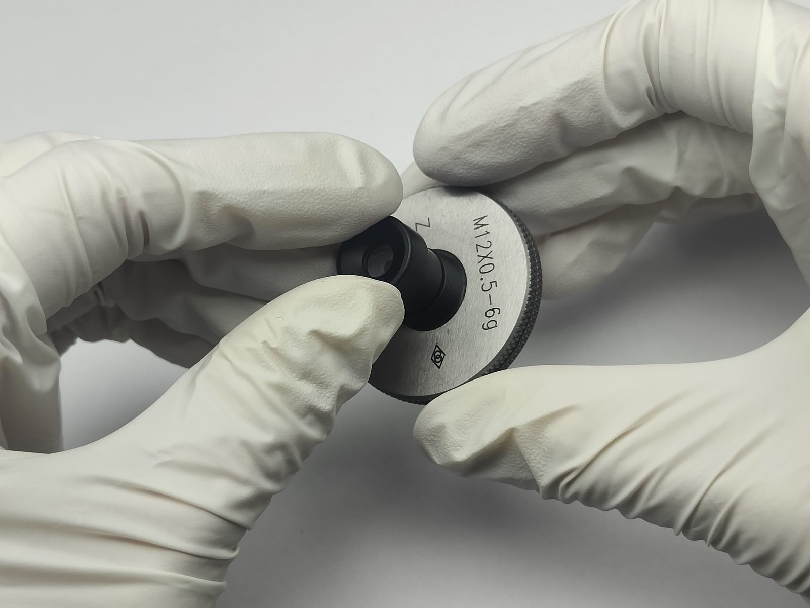
The mechanical interface decides how much of the optical budget your housing keeps. On a threaded M12 (S-mount) interface, barrel-to-bore clearance and shoulder squareness set the practical limits, and thread locking matters as much as nominal fit on a machine that vibrates. On a C-mount interface the seating face and the flange-to-axis perpendicularity set tilt. Flange focal distance is 17.526 mm on C-mount against 12.5 mm on CS-mount, so a 5 mm adapter ring changes the mechanical stack and belongs in the same sum. Ask for the interface drawing with seating face flatness, runout, bore-to-datum concentricity, thread specification and thermal expansion coefficients, then subtract the maker’s contribution from the total to see what is left for your housing, your adhesive and your assembly fixtures.
Measured assembly alignment, not element tolerances. Ask for the finished lens measured against the mounting datum you both name: X and Y decenter, X and Y tilt, axial position or flange-to-image-plane distance, boresight, and image-plane tilt. Individual element centering numbers cannot be summed into a net axis error, because internal compensation and active alignment remove part of that error during build. A maker with centration and focus-position instruments in the assembly cell, such as the Trioptics centration and OptiSurf systems named on our own metrology list, can measure the assembled axis directly instead of reporting a stack of part tolerances and leaving the sum to you.
Distributions and correlations. A limit is not a distribution. Ask for the mean, the standard deviation, minimum and maximum, percentiles (P1, P50, P99), the correlation between tilt and decenter, and how far the process moves between lots. Ask what yield basis the quoted limit is tied to. Two suppliers can both claim a 0.1 degree tilt limit while one ships distributions three times tighter than the other, and only the distribution tells you which one you are buying.
Sensitivity, at named field points and named frequencies. This is the item most often absent from a quotation. Ask for the change in MTF or spot size per micron of decenter and per arcmin of tilt at the image center, at 70 percent field and at the corner, sagittal and tangential separated, at the spatial frequency your requirement names. Modulation transfer is contrast as a function of spatial frequency, described in the standard treatment of the optical transfer function, so a single MTF number without its frequency is not a specification at all. Ask whether the numbers are before or after focus compensation, and ask what alignment error is already inside the MTF curve the maker published. If that last answer is vague, you will either double count the lens contribution or hand your housing more tolerance than the optics can support. Read the table the way you would read any MTF chart: without the frequency, the field and the orientation, the number cannot be compared with anything else.
Measurement uncertainty, and the axial numbers. Ask for the uncertainty and repeatability of the maker’s own measurement, so their gauge error is not charged to your housing budget. Alongside the alignment figures, request back focal distance with its tolerance, exit pupil position, the image-space chief ray angle against image height, and the focus position used for each measurement. The impact of lens chief ray angle on sensor alignment is easy to underestimate: tilt and decenter change the incidence angle seen by the sensor microlenses, and a large chief ray angle at the corner turns a small mechanical error into shading and crosstalk, not just blur.
The minimum package, and what to do when the design file is refused. Most lens makers will not release a prescription or a tolerance model, and that is a defensible commercial position. Offer an NDA, then ask for a two page extract instead: the datum definition, a measured alignment sample from production, the sensitivity table, and the measurement uncertainty. That extract is enough to run your own combined model, and it is a smaller ask than the full design file, which makes it more likely to arrive before your drawing review rather than after it.
The usual mistake is to take one permitted MTF loss and divide it equally between lens tilt, lens decenter, sensor tilt, sensor decenter and axial error. The contributors do not act alike. Axial error defocuses the whole field and shows at the center first. Tilt creates a focus gradient that grows toward the corner. Decenter shifts the image and unbalances the field. A sensor alignment budget specification that gives the corner the same allowance as the center will pass on paper and fail on the bench.
Root sum square is valid only where the image response is linear in each variable and the variables are independent. Tilt and decenter are often correlated, because one assembly operation produces both, and tilt sensitivity is field dependent, so the linear assumption breaks exactly where the budget is tightest. Ask for the correlations, keep the field dimension inside the model, and combine in a Monte Carlo run on the image metric rather than on the mechanical values. The output of that run is a predicted yield at your requirement, which is what the program needs, not a stack of tolerance symbols.
Decide what you will compensate before you set limits. If production can tilt the sensor or adjust focus, the budget should use the residual after that adjustment, not the raw mechanical error, because a single axial focus adjustment cannot remove a field dependent focus gradient. If you intend to tilt the sensor to cancel lens tilt, request the lens tilt pivot so that your adjuster geometry and the maker’s datum describe the same motion. State the compensation you plan to perform, and ask for the residual after it.
The sensor belongs in the same request. Your sensor has its own tilt and decenter distribution, a cover glass thickness the lens was designed around, and a microlens acceptance angle. Those three set a floor on total blur that no lens tolerance can go below, and cover glass thickness shifts the effective focus position, so confirm it before you finalize the back focal distance you ask the maker to hold.
Every figure you requested is a claim until it is measured on hardware. Put the first article on a collimator or autocollimator fixture, measure boresight, X and Y tilt and axial position against the datum you specified, and run MTF at the same field points the maker used. When the two sets of numbers disagree, the cause is usually the datum rather than the lens: the two parties are measuring from different surfaces and calling both results tilt.
Ask for batch-linked reports rather than a single sample report. On our own FA line every production batch ships with test documentation covering the agreed family parameters, typically MTF, distortion, BFL and DOF, plus the batch number, the test conditions, the inspection coverage and an explicit pass or fail judgment. That is the pattern worth writing into a specification: numbers tied to a batch, at stated conditions, with a judgment attached. A report full of curves and no conditions is not evidence of anything.
Keep the as-installed record. The values measured on the first article, after your own assembly process, become the baseline for everything that follows. When a later unit underperforms, that record separates a lens that moved from a housing that moved, and you avoid replacing good optics to fix a mechanical problem. The same record tells you whether a new lens lot quietly changed your alignment budget, which is the question that arrives at every quoting round.
Finally, ask how alignment moves after thermal cycling, shock and vibration, and adhesive cure, with worst case and statistical drift reported separately. A lens that meets alignment at room temperature can consume far more of the budget in the field. The test of a good data package is simple: every number sits in one coordinate frame, every number carries a distribution, and every number has an image quality effect stated at the field point where it hurts. What you are asking the maker for is a page of measured data, not a promise.

LED flicker after a power supply swap is an electrical-to-exposure matching miss. Lock lighting electrical specs to the camera exposure plan before the next...
read more…
A telecentricity bench proof pack is the acceptance file that turns a datasheet telecentric claim into measured magnification-versus-object-distance curves and written reject limits before...
read more…
An illumination pupil pack is the optical data set that tells a lighting designer where the lens aperture stop and entrance pupil sit before...
read more…