Splitting a scope into a tip objective and a relay only works if the interface between them is treated as a controlled document rather than a place where two suppliers meet. The interface sheet should fix the conjugate condition first, because everything else follows from it: whether the objective forms a real intermediate image at a stated plane, or is corrected for infinity and needs a tube lens before an intermediate image exists. Once that is settled, the relay needs the intermediate image position and size, the image-space numerical aperture, the pupil location and diameter, a chief-ray angle map across the field, the clear aperture, and the wavelength range over which those figures hold. Add the mechanical datum and each half can be specified, sourced and tested on its own.
If you are comparing suppliers for this kind of optic, the Lensmind machine vision lens catalog is the hub for our standard models and custom options.
Decide the Conjugate Condition First
The most expensive mistake in a split scope is agreeing the interface before agreeing which optical condition the objective is designed for. A finite-conjugate objective forms a real image at a defined distance behind its last surface. An infinity-corrected objective collimates the beam and forms no image at all until a tube lens brings it to focus, which means the intermediate image position belongs to the tube lens rather than to the objective. Two suppliers designing to different assumptions will each deliver a correct component that cannot work with the other, and the fault will appear at the integration bench rather than on the drawing.
Write the condition down as a sentence plus a figure: the objective is finite conjugate, with a real image at a stated distance from a named mechanical face, or the objective is infinity corrected and the intermediate image is formed by a tube lens of a stated focal length at a stated plane. Then state who supplies the tube lens and who owns the focal length. That single decision determines what the relay is asked to re-image, and it is the first line of the interface sheet.
The Optical Data the Relay Needs
The relay’s job is to take the objective’s output and deliver it to the sensor with the right magnification and image quality, and it has to do that for the whole field, not just the axis. The objective’s numerical aperture sets the relay’s aperture, and the image-space numerical aperture at the intermediate image tells the relay designer how much light has to be collected and how steep the cone is at each field point. If the interface sheet states only focal length and magnification, the relay is being designed against half its inputs.
The relay lens also has to place the pupil correctly, because the pupil is where the aperture stop sits in image space, and a relay that puts the stop in the wrong place will vignette the field or shift the image as the aperture changes. Supply the exit pupil location and diameter as measured from the objective’s last mechanical face, and add the chief-ray angle as a function of field height, because the sensor’s response and the microlens array both care about incidence angle. If the objective is close to image-space telecentric, say so with a number rather than a word: the maximum chief-ray angle at the largest image height you intend to use.
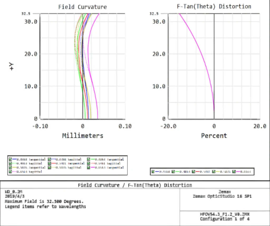
Then add the performance figures the relay has to preserve. Distortion and field curvature at the intermediate image, transmission and coating design over the wavelength band, and any field-dependent focus shift that the objective introduces. Where a scope has to work across a band, the chromatic behaviour at the interface belongs in the sheet, because the relay cannot correct a longitudinal shift it cannot see.
Mechanical Datum and the Interface Drawing
The mechanical interface is where a good optical design becomes two parts that actually assemble. Define the datum: the face or diameter that locates the objective in the tip assembly, the datum that locates the relay at its end, and the axial distance between the two datums once assembled. Give the tolerances on the intermediate image plane position, on the decenter between the two axes, and on the tilt at the joint, because those three numbers are the ones that decide whether the assembled scope holds its image quality.
Put the interface on a drawing that both suppliers sign, using a recognised optical drawing convention for the optical surfaces and a normal mechanical convention for the mount. The drawing should show the intermediate image plane as a physical, measurable reference, not as a calculated plane that exists only in the design file. A plane nobody can measure is a plane nobody can inspect, and inspection is the point of the exercise.
Testing the Objective Alone, and the Relay Alone
The whole reason to split the scope is that each half can be tested by its own supplier before integration, and that only works if each test is defined against the interface. The objective is tested at its own conjugate, with a target at the design object distance and a measurement of the intermediate image: resolution at named field points, distortion, and the position of the image plane relative to the mechanical datum. It is not tested at the sensor, because the sensor is not part of its scope.
The relay is tested against a source that mimics the objective’s output: the correct numerical aperture, the correct field, the correct pupil position, and the correct wavelength band. A relay tested with a convenient collimated source and no field may pass on the bench and fail in the assembled tip, because the field and the pupil are exactly what the interface sheet was supposed to nail down.
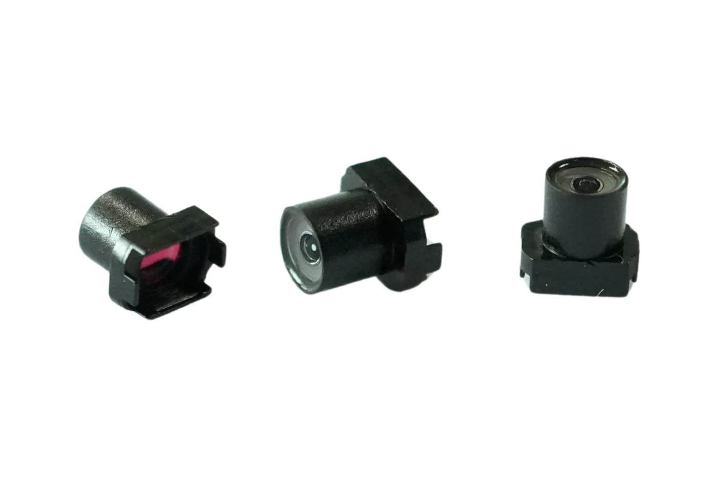
An endoscope family that pairs sensors such as OV9734, OV2740 and ES101 with sub-2 mm objectives is a good reminder of how small these margins are. At that scale the interface data is not paperwork that follows the design; it is the reason the two halves can be built at all, because nobody can iterate a tip assembly by trial and error at that size. Medical and industrial scopes share that interface logic even when the enclosure and the cleaning regime differ, which is the ground covered in medical endoscope OEM lenses.
The Responsibility Line
Write down who owns what, per parameter, and keep the list short enough to be read. The objective supplier owns the intermediate image position, its quality across the field, and the pupil data at the interface. The relay supplier owns the magnification to the sensor, the image quality at the sensor, and the back focal distance to the sensor window. The integrator owns the assembly tolerances between the two datums, the final focus, and the acceptance test on the assembled scope.
The line matters when something is wrong, because the failure usually shows up in the assembled system where both halves are implicated. With the interface data and the two separate test reports, the question becomes specific: the intermediate image was at the specified plane when the objective left the factory, so either the assembly moved it or the relay does not accept it there. Without the data, the conversation is a disagreement about whose bench is wrong.
The Interface Pack a Small Scope Program Should Ask For
For a program that is new to splitting a scope, the pack is smaller than the optical theory suggests. Ask for the conjugate condition statement, the intermediate image plane definition with its mechanical reference, the image-space numerical aperture and pupil data, the chief-ray angle table across the field, the clear aperture, the wavelength band with transmission, the distortion and field curvature at the interface, the mechanical datum drawing with the three tolerances, the objective test method and the relay test method. Add the change control rule: neither half may change a parameter on that list without a revised interface sheet agreed by both sides.
A maker who already builds both halves can supply this pack from existing design data, and that is the practical advantage of sourcing a split scope from one optical house even when the two halves are manufactured separately. It also shortens the commercial path: a custom optics enquiry can be answered with a feasibility first pass within 48 hours under NDA, and a prototype to mass production programme is quoted against a written 60 working day standard commitment, so the interface document is what keeps that schedule from being spent on integration surprises.
Freeze the Interface Before Either Half Is Released
Freeze the interface sheet at the same time as the drawing that defines the mechanical joint, and treat any change to it as a change to both halves. A relay redesign that moves the pupil, an objective change that shifts the intermediate image plane by a fraction of a millimetre, or a sensor change that alters the required back focus all invalidate the other half’s test criteria, and each of them is cheap to approve at the desk and expensive to discover at the integration bench.
The freeze is also what makes the split worth doing. Two suppliers working to a frozen interface can be qualified independently, re-qualified independently after a change, and held to their own test reports. Two suppliers working to a conversation will deliver two good components and one bad scope. The interface sheet, the drawing and the two test methods are the whole deliverable, and they should be signed before either half goes into tooling. Programs that document the interface this way can also compare bids honestly, which is the subject of the endoscope RFQ that makes bids comparable, and they can specify a distortion margin at sub-2 mm objectives that a vendor can actually accept, as covered in scope lens distortion margins.
Written by Baker Zhao, Founder at Lensmind Optics.